
Reconfigurable variable length FIR filters for optimizing performance of digital repeater

A reconfiguration and filter technology, applied in digital technology networks, complex mathematical operations, electrical components, etc., can solve the problem that the FIR filter structure does not meet the needs of repeaters

Inactive Publication Date: 2015-04-29
INTEL CORP
View PDF9 Cites 4 Cited by
  • Summary
  • Abstract
  • Description
  • Claims
  • Application Information

AI Technical Summary

Problems solved by technology

First, the regulator limits the out-of-band gain, and thus the "gain" of the repeater
Second, larger gains in adjacent bands mean that a certain signal in the band of interest can sneak in through adjacent band filters and interfere at the common output, causing EVM
And thus a fixed FIR filter structure is not suitable for all different repeater needs

Method used

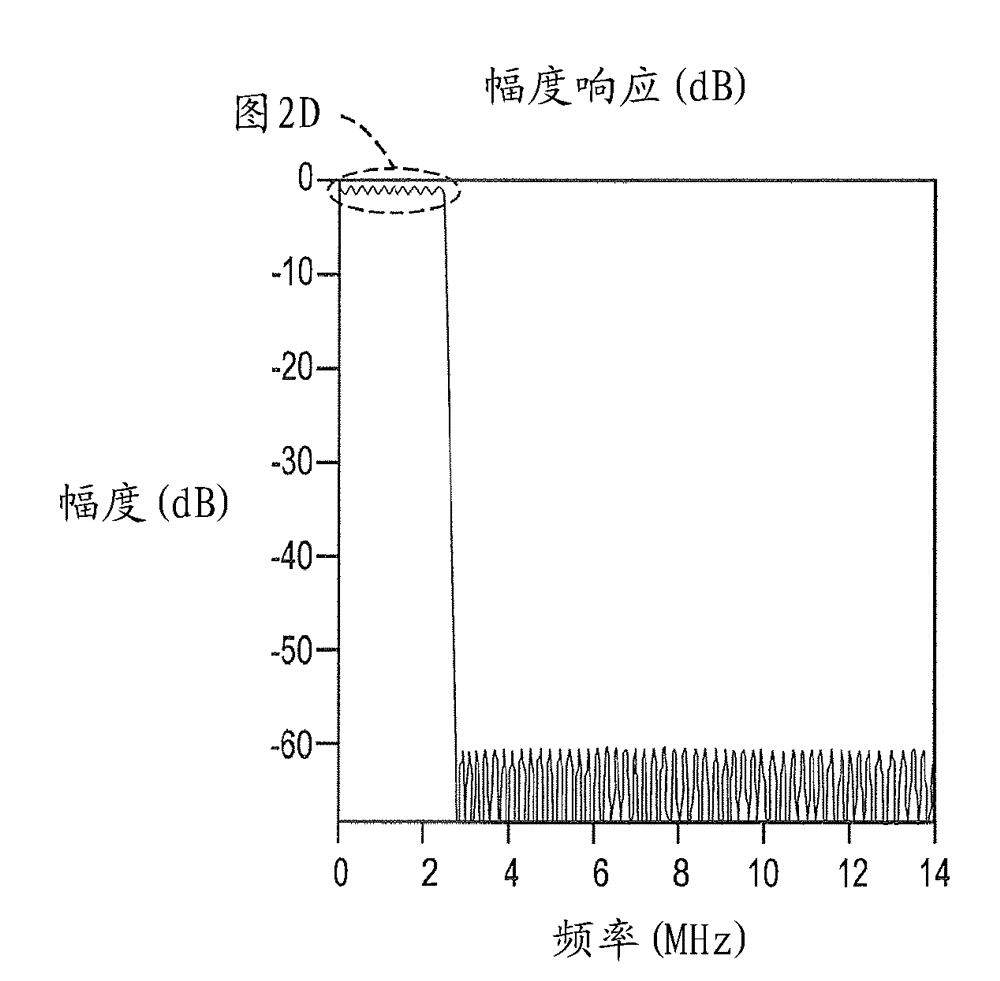
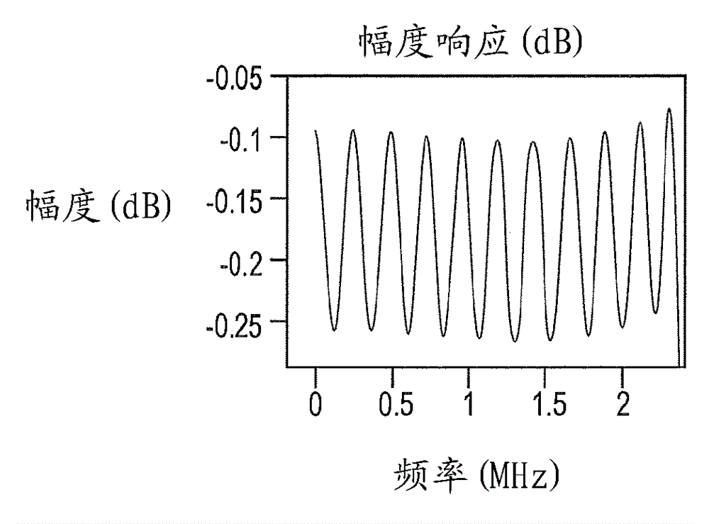
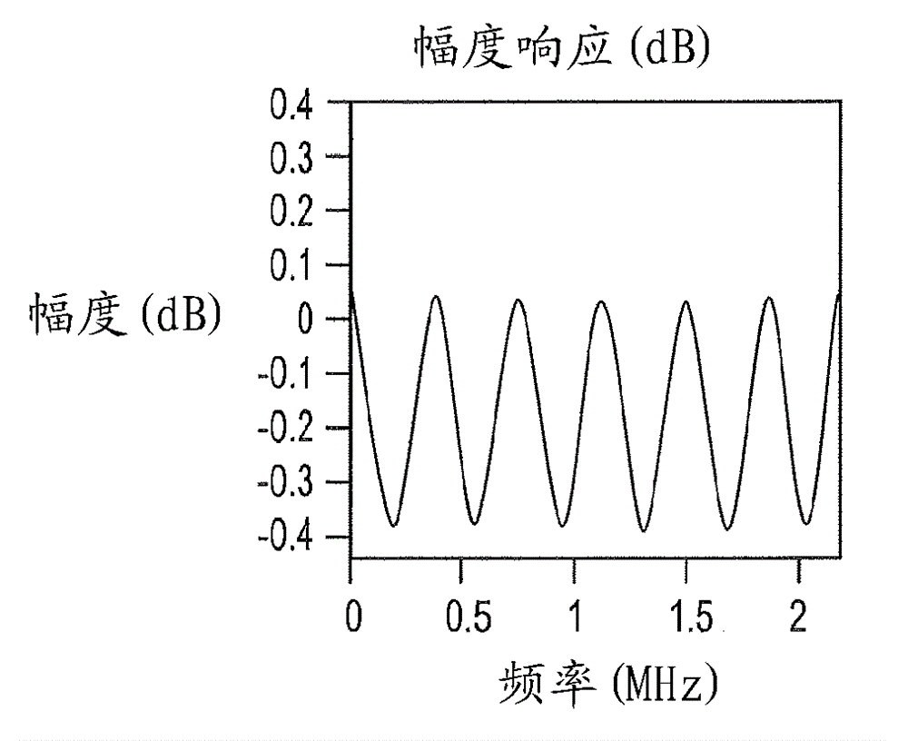

Image

  • Reconfigurable variable length FIR filters for optimizing performance of digital repeater
  • Reconfigurable variable length FIR filters for optimizing performance of digital repeater
  • Reconfigurable variable length FIR filters for optimizing performance of digital repeater

Examples


Embodiment Construction

[0019] The present invention is directed to providing a digitizer 10 employing reconfigurable variable length FIR filters. refer to Figure 4 , showing the architecture of the repeater 10 . The repeater 10 includes two main blocks, the donor component 12 and the service component 14 . Each consists of: a) a duplexer 16, implemented using the same antenna for reception and transmission; b) a low noise amplifier (LNA) 18; c) a power amplifier (PA) 20; d) a radio frequency (RF) receive section 22; e) RF transmit section 24; f) analog-to-digital controller (ADC) 26, which converts analog signals into digital for further signal processing done in digital form; g) digital processing section 28 for sub- with filtering and gain control; h) a main control unit (MCU) 30 or main processing controller for receiving and sending instructions from and to other components of the repeater 10; and i) digital to analog (DAC) 32 to convert the digital signal back to analog after digital signal...


PUM


Abstract

The invention addresses the problem of parameter optimization for best filter performance and, in particular, the influence from the requirements on radio or fiber to radio repeaters utilizing those filters, that often proves to be conflicting for an FIR filter. The FIR filters are implemented in a programmable circuit and are not thereby restricted for use in communication repeaters although this particular usage may put the most serious restrictions on the filter performance. Within the imposed constraints, this disclosure illustrates a method to strike a middle ground while minimizing the trade-offs. The advantage of the concept presented allows the choice of a suitable filter pertaining to a particular traffic configuration, meaning a particular choice of individually filtered frequency bands set at different gain and intended to support a diversity of traffic formats. The disclosed approach banks on the reconfigurable variable length FIR filter architectures. Implementation architecture and results in brief are also presented.

Description

Background technique [0001] Repeaters are deployed to increase the coverage area of ​​wireless communication systems. A repeater consists of two components: a donor and a service. The donor component receives data from the donor base station, amplifies, filters the received signal, and transmits the amplified and filtered signal from the radio unit. Communication with the base station is done via the donor antenna. The service component receives data from the serving radio, amplifies and filters the received signal, and transmits the amplified and filtered signal from the base station. Communication with the radio unit is done via the serving antenna. [0002] Repeaters use finite impulse response (FIR) filters as part of the signal processing. Typically, FIR filter synthesis is constrained by passband ripple, stopband rejection, roll-off, group delay (GD), and group delay distortion (GDD). The distortion imposed by the filter on the signal results in an increase in the e...

Claims


Application Information

Patent Timeline
Patent Type & Authority Applications(China)
IPC IPC(8): G06F17/10
CPCH03H17/0294H03H17/06G06F17/10
Inventor M. 乔格丹德S. 布哈米德帕蒂J. 尤帕T. 奥斯森
Owner INTEL CORP
Learn More