
Scalable-voltage current-link power electronic system for multi-phase AC or DC loads

A technology of power electronic module and electronic power, which is applied in the direction of high-efficiency power electronic conversion, irreversible DC power input conversion to AC power output, and AC power input conversion to DC power output, etc., which can solve the switching frequency limitation and the cost is not feasible And other issues

Inactive Publication Date: 2015-04-29
GENERAL ELECTRIC CO
View PDF4 Cites 9 Cited by
  • Summary
  • Abstract
  • Description
  • Claims
  • Application Information

AI Technical Summary

Problems solved by technology

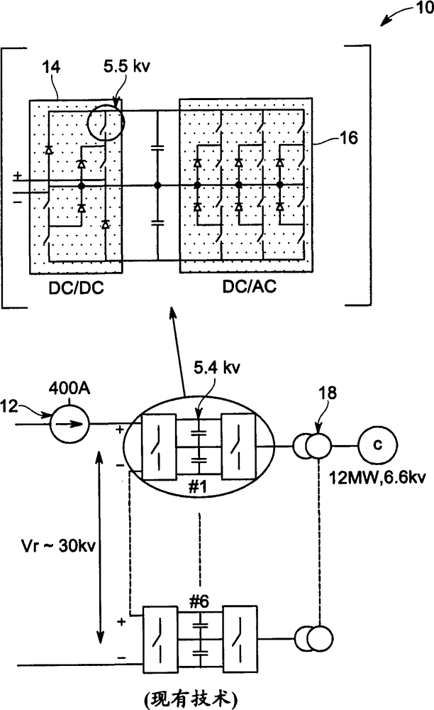
[0005] exist figure 1 A disadvantage of the state-of-the-art system depicted in is that the switching frequency (typically 400-600Hz) of a 5.5kV device is limited due to thermal management requirements
However, if power density is an advanced requirement, e.g. for subsea oil and gas applications, the added cost on the number of low frequency transformers mentioned above may not be feasible

Method used


Image

  • Scalable-voltage current-link power electronic system for multi-phase AC or DC loads
  • Scalable-voltage current-link power electronic system for multi-phase AC or DC loads
  • Scalable-voltage current-link power electronic system for multi-phase AC or DC loads

Examples


Embodiment Construction

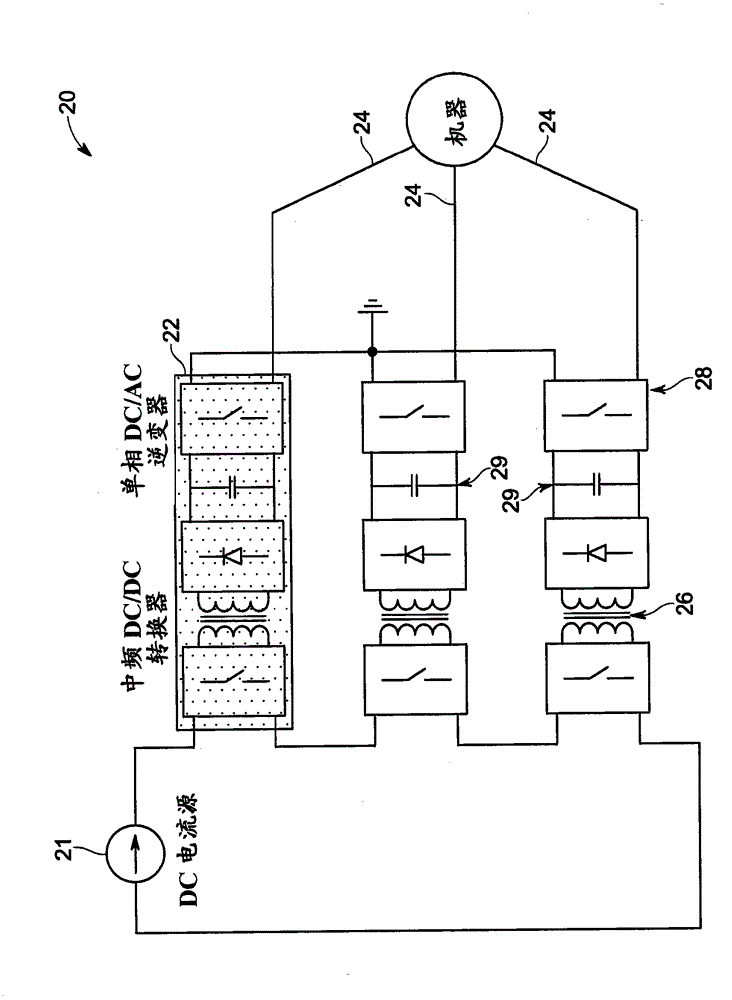
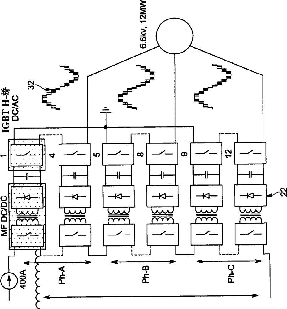
[0030] refer to figure 2 , shows an exemplary multi-megawatt modular three-phase drive system 2 using state-of-the-art technology. The same power electronics module 22 is used to generate the AC voltage at the machine end 24 . However, as described herein, multiple modules 22 can be used to generate n-phase DC or AC outputs. Module 22 includes a medium / high frequency isolated DC / DC current to voltage converter 26 and a single phase DC / AC converter 28 . The DC / DC and DC / AC converters 26 , 28 are connected back to back, sharing the same dc link 29 . refer to this article Figure 4-11 A more detailed description of the DC / DC converter 26 and the DC / AC converter 28 is presented.

[0031] Those skilled in the art of transformers will understand that for a particular application, a higher excitation frequency of the transformer will allow a reduction in its size and weight. Therefore, each module 22 is expected to have a high power density. continue to refer figure 2 , usin...


PUM


Abstract

An electronics power system includes a plurality of substantially identical power electronic modules. Each power electronic module includes a single-phase DC / AC inverter having an output side. Each power electronic module further includes a medium / high-frequency-isolated DC / DC current-to-voltage converter having an input side. The medium / high-frequency-isolated DC / DC current-to-voltage converter drives the single-phase DC / AC inverter. Each DC / DC converter and its corresponding DC / AC inverter are connected back-to-back sharing a common DC-link. The plurality of power electronics modules is stacked together in series at the input side and in parallel or series / parallel at the output side.

Description

Background technique [0001] The subject matter of the present disclosure relates generally to power electronics systems, and more particularly to scalable voltage-current link power electronics systems suitable for use in high voltage megawatt drives, current link based high voltage DC (HVDC) taps, Used in megawatt drives for subsea oil and gas, and in HVDC power transmission and distribution (HVTD). [0002] For an exemplary current link system, the distance between the source (three-phase 60Hz grid) and the load (eg many compressor drives, each P > 10MW) may be greater than 100km. The three-phase grid voltage on the source side is actively rectified and converted into a constant current source. A current source inverter (CSI) on the load side can be used to generate a three-phase voltage on the load terminals. Therefore, power is supplied through a current-link based DC transmission system similar to classical HVDC. The value of the current source is limited by two fac...

Claims


Application Information

Patent Timeline
Patent Type & Authority Applications(China)
IPC IPC(8): H02M7/48H02J3/36H02M7/49
CPCH02M7/4807H02M7/487H02M7/49H02M1/0074H02M1/0077H02M7/4818Y02B70/10
Inventor R·K·古普塔R·N·拉朱R·达塔M·阿加米
Owner GENERAL ELECTRIC CO
Learn More