Drying machine and dish washing machine

A technology of drying device and exhaust motor, which is applied to the parts of washing machine/rinsing and washing machine for tableware, etc. It can solve the problems of potential safety hazards, high energy consumption, and poor drying effect, so as to improve the drying effect and reduce energy consumption , the effect of simple structure

Active Publication Date: 2015-05-06
WUHU MIDEA SMART KITCHEN APPLIANCE MFG CO LTD
View PDF5 Cites 27 Cited by
  • Summary
  • Abstract
  • Description
  • Claims
  • Application Information

AI Technical Summary

Problems solved by technology

[0004] The purpose of the present invention is to provide a drying device, aiming to solve the problems of poor drying effect, high energy consumption and potential safety hazards of the drying device in the dishwasher in the prior art

Method used


Image

  • Drying machine and dish washing machine
  • Drying machine and dish washing machine
  • Drying machine and dish washing machine

Examples


Embodiment 1

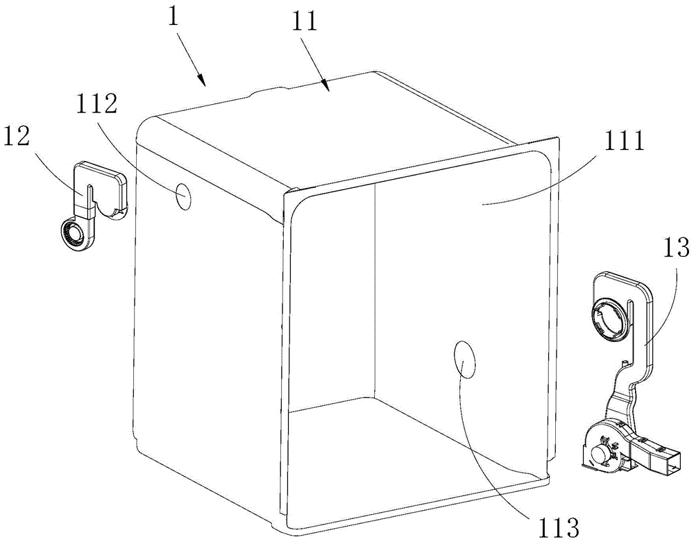
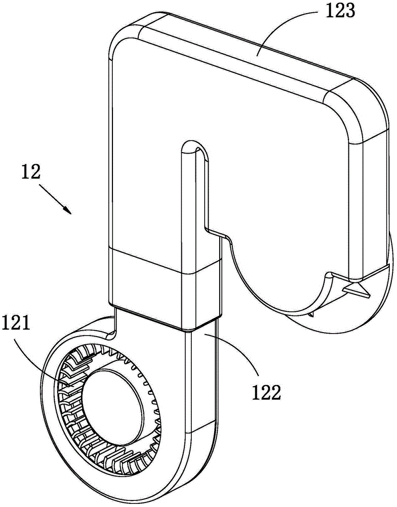
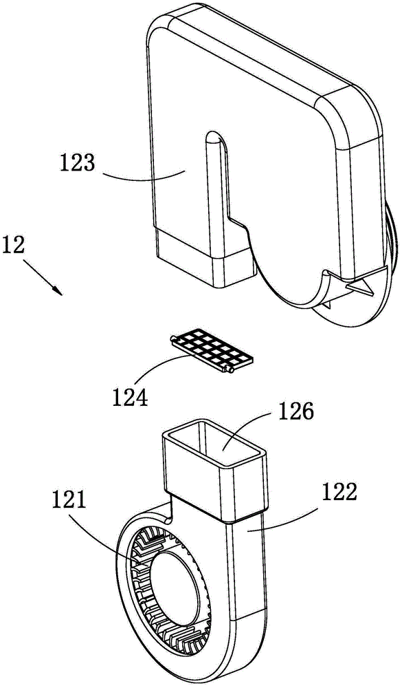
[0026] Such as Figure 1-10 Shown is a preferred embodiment provided by the present invention.

[0027] The drying device 1 provided in this embodiment can be used in a dishwasher, of course, it can also be used in other equipment, such as some equipment that needs to dry the inner cavity 111, can be operated by using the drying device 1, And it's not just limited to dishwashers.

[0028] The drying device 1 comprises an inner container 11, an air inlet mechanism 12 and an exhaust mechanism 13, wherein the inner container 11 is in a square shape, and a cavity 111 is provided therein, and one side of the cavity 111 has an opening, and objects to be washed can be placed in the In the cavity 111 of the inner container 11, thereby, utilize other components to close the opening of the cavity 111, then the inner container 11 can be in a closed state, and steam can be used to wash the objects to be washed in the cavity 111; The shape of the bladder 11 is not limited to the above-me...

Embodiment 2

[0061] Such as Figures 11 to 14 Shown is another preferred embodiment provided by the present invention.

[0062] The difference between this embodiment and Embodiment 1 is:

[0063] In this embodiment, the baffle 124 is arranged in the connecting port 120 of the air duct 123, and the step 129 is also arranged in the connecting port 120, the baffle 124 can be abutted on the step 129, and one side thereof is hingedly arranged, thus, The baffle 124 can swing in the connection port 120 to realize the closing or opening of the air duct.

[0064] Specifically, a hinge seat 127 is provided on the step 129, and a pin shaft 128 extends outward from one side of the baffle plate 124, so that the pin shaft 128 is hinged in the hinge seat 127 to realize the hinge arrangement on one side of the baffle plate 124. . Such as Figure 13 As shown, it is a schematic diagram of the air passage closed by the baffle plate 124, such as Figure 14 Shown is a schematic diagram of the baffle 13 o...


PUM


Abstract

The invention relates to the technical field of dish washing machines, and provides a drying machine and a dish washing machine. The drying machine comprises an inner container, the side wall of the inner container is connected with an air inlet mechanism and an exhaust mechanism, the air inlet mechanism comprises an air inlet pipe, the side wall of the inner container is provided with an air inlet hole and an exhaust hole, the air inlet hole and the exhaust hole are distributed at different heights, and the air inlet pipe is connected with the air inlet hole; the exhaust mechanism comprises an exhaust motor and an exhaust pipe, and the two ends of the exhaust pipe are connected with the exhaust motor and the exhaust hole respectively. After tableware in the dish washing machine is rinsed, outside air enters the inner container through the air inlet hole, the exhaust motor pumps the air in the inner container through the exhaust hole, and the air is exhausted outside through the exhaust pipe; the air inlet hole and the exhaust hole are distributed at different heights, so that air convection is formed in the inner container, the drying effect is greatly improved, energy consumption is lowered, air convection is smooth, noise is low, the structure is simple, and potential safety hazards are avoided.

Description

technical field [0001] The invention relates to the technical field of dishwashers, in particular to a drying device and a dishwasher including the drying device. Background technique [0002] At present, it is necessary to install a drying device in the dishwasher for drying the washed tableware. [0003] In the prior art, waste heat drying and single fan drying are widely used as drying devices in dishwashers, and zeolite drying is used in some high-end dishwashers. Waste heat drying requires high rinsing temperature, resulting in a waste of energy. In today's society with high energy-saving and environmental protection requirements, the living space of high-energy-consuming appliances is getting smaller and smaller, and the drying effect is poor and easy to rebound. The temperature and humidity in the inner tank of the machine are high. During the cooling process, water vapor is easy to condense on the tableware. If the dishwasher is not used for a few days, mold will gr...

Claims


Application Information

Patent Timeline
Patent Type & Authority Applications(China)
IPC IPC(8): A47L15/48
Inventor 高峰扶菁林周海国
Owner WUHU MIDEA SMART KITCHEN APPLIANCE MFG CO LTD
Why Eureka
Try Eureka