Eureka AIR delivers breakthrough ideas for toughest innovation challenges, trusted by R&D personnel around the world.

Surface treatment device for sand core of housing

A technology of surface treatment device and sand core, which is applied in casting molding equipment, metal processing equipment, manufacturing tools, etc. It can solve the problems of affecting gas flow, affecting the size of inner flow channel, and uneven coating quality, so as to improve the working environment, Improve work efficiency and optimize personnel settings

Active Publication Date: 2015-05-06
西峡县众德汽车部件有限公司
View PDF5 Cites 7 Cited by
  • Summary
  • Abstract
  • Description
  • Claims
  • Application Information

AI Technical Summary

Problems solved by technology

[0004] 1. The coating is static, the quality of the coating is uneven, and the coating thickness of the coating is unstable, which affects the size of the inner flow channel and greatly affects the gas flow, resulting in unstable engine performance;
[0005] 2. Manual operation is adopted, and the trajectory of the sand core is uncontrollable;
[0006] 3. Using manual operation, the jitter intensity is uncontrollable, and the production efficiency is low, which is not suitable for large-scale production
[0007] This is the common problem of most auto parts enterprises, which seriously restricts the profitability of enterprises.

Method used


Image

  • Surface treatment device for sand core of housing
  • Surface treatment device for sand core of housing

Examples


Embodiment approach

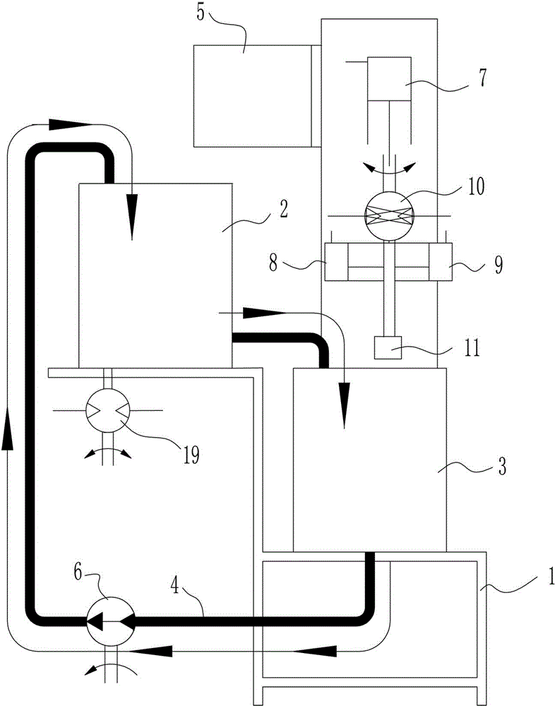
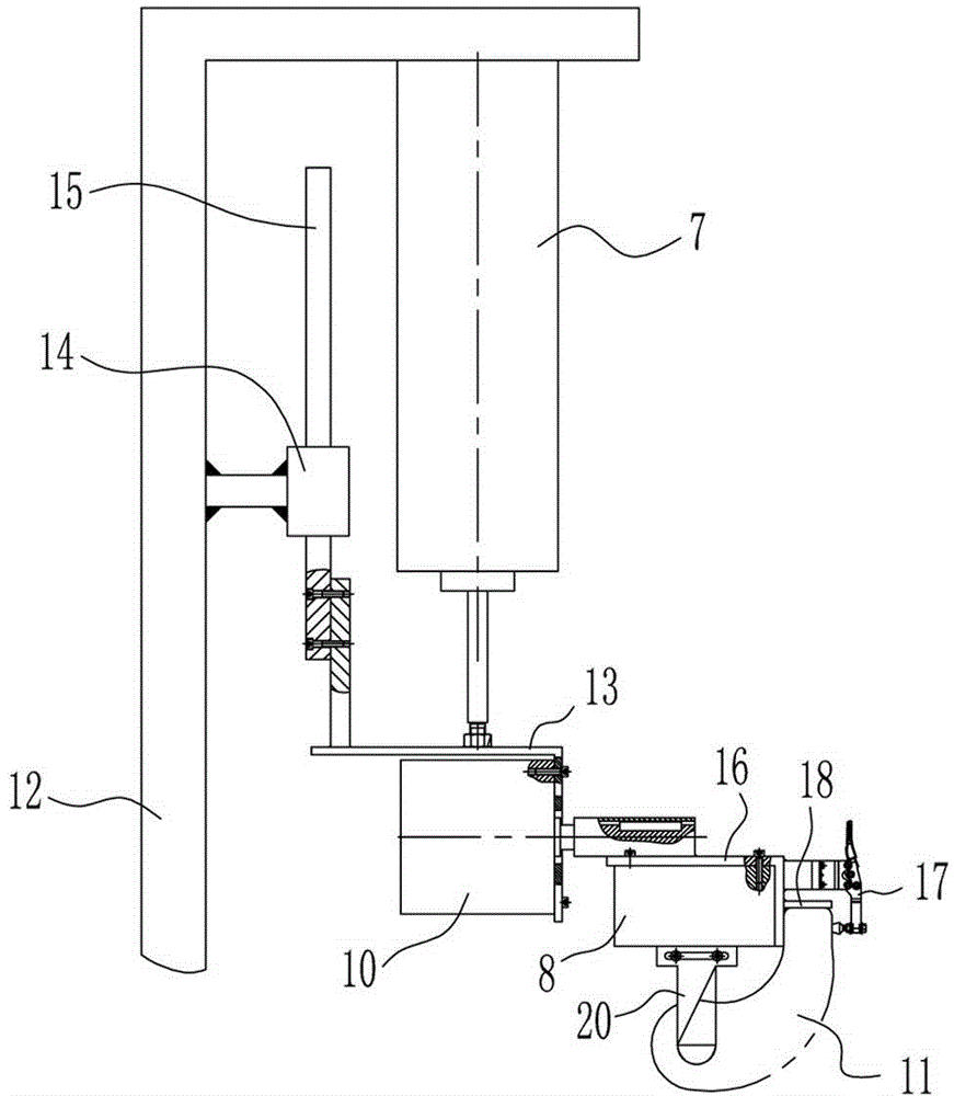
[0025] A preferred embodiment, the driving device includes a first cylinder 7 and a fixed seat 13, the first cylinder 7 is fixed on the bracket 12 on one side of the support seat 1, and the fixed seat 13 is fixed on the lower end of the cylinder rod of the first cylinder 7, During operation, the tooling fixture can be installed on the fixed seat 3, and the PLC control system 5 controls the corresponding solenoid valve of the first cylinder 7 to control the intake and exhaust of the first cylinder 7 and then control the extension length of the cylinder rod of the first cylinder 7 And extend the residence time to control the dip-coating treatment on the surface of the sand core, and the first cylinder of the driving device can also be replaced by a hydraulic cylinder.

[0026] Preferably, the bracket 12 is provided with a guide rail seat 14, and the top of the fixed seat 13 is provided with a guide rail 15 matching with the guide rail seat 14, so that the overall operation of the...


PUM


Abstract

The invention discloses a surface treatment device for a sand core of a housing. The device mainly comprises a supporting base, a tool clamp, a driving device and a PLC control system as well as a stirring tank and a dip-coating tank which are arranged on the supporting base, wherein the stirring tank is communicated with the dip-coating tank by virtue of a pipeline to form a closed loop; a hydraulic pump is arranged on the pipeline; the tool clamp is arranged above the dip-coating tank and is fixedly arranged on the lower end part of the driving device; the PLC control system is electrically connected with the tool clamp and the driving device; the PLC control system controls the tool clamp to clamp the sand core and controls the driving device to penetrate the clamped sand core into the dip-coating tank to be dip-coated. According to the surface treatment device disclosed by the invention, the coating in the dip-coating tank is still in a dynamic state, the sand core is clamped by virtue of the tool clamp and the moving trajectory of the sand core is controlled by virtue of the driving device, and the time of dip-coating the sand core is controlled, so that a consistent surface coating thickness is obtained, and therefore, the stability of the product dimension is facilitated; moreover, the working environment of the operator is effectively improved, personnel allocation is optimized, and the work efficiency is greatly improved.

Description

technical field [0001] The invention relates to a sand core surface treatment device, in particular to a shell sand core surface treatment device. Background technique [0002] With the improvement of environmental protection requirements and the development of automobile manufacturing technology, the technical requirements for the key component-engine are more stringent. In addition, the extensive application of turbocharging technology has put forward more stringent indicators for the standards of engine-related supporting products. Especially turbocharger housing and bearing housing products. [0003] Core making is particularly critical during the production of turbocharger housings and bearing housings. Because the sand core obtained from core making involves the quality of the inner runner of the product, including surface finish and dimensional stability. This is very critical to the working stability of the engine. For this reason, it is necessary to use paint for...

Claims


Application Information

Patent Timeline
Patent Type & Authority Applications(China)
IPC IPC(8): B22C23/02
CPCB22C23/02
Inventor 李平衡张启奎李英园裴雪健
Owner 西峡县众德汽车部件有限公司
Why Eureka
Eureka Blog
Learn More