

Integrated beam-slab-column formwork structural system and construction method
A construction method and technology of column formwork, which are applied in the direction of building structure and construction, can solve the problem that the connection effect of beam-column joints is difficult to reach the degree of cast-in-place, the plastering layer and the concrete surface are not firmly bonded, and the quality of components is greatly affected, etc. problems, to achieve the effect of firm splicing construction method, strong frame structure integrity, and improved force transmission performance of beam-column joints
Active Publication Date: 2015-05-06
JINAN RAILWAY TRANSPORT GRP CO LTD
View PDF7 Cites 11 Cited by
- Summary
- Abstract
- Description
- Claims
- Application Information
AI Technical Summary
Problems solved by technology
[0002] The traditional construction sequence of the frame structure is to tie the steel bars-support the formwork-pour the concrete-remove the formwork. This process is not only labor-intensive and material-intensive, but also the construction is relatively complicated. The quality of the components is greatly affected when the formwork is removed. Decoration, the plaster layer and the concrete surface are not bonded firmly, and hollowing cracks are easy to occur, which takes a long time and costs a lot. For large-scale steel formwork pouring, large-scale hoisting equipment must be used for its installation and removal, and the safety risk factor is high. ;The emergence of prefabricated components has brought factoryization into the construction field, shortening the construction period, but the connection effect of beam-column joints is difficult to reach the level of cast-in-place, which affects the seismic performance of the entire structure
Method used
View moreImage
Smart ImageViewing Examples


Examples
Embodiment 2
[0056] The beam formwork in embodiment 2 is composed of a formwork unit (such as Figure 13 As shown), the two ends are spliced with the formed beam-column joint formwork through concave-convex grooves, and the upper part of the side wall has a pair of tie rods 121. The rest of the construction steps are similar to those in Embodiment 1 and will not be described again.
Login to View More PUM
 Abstract
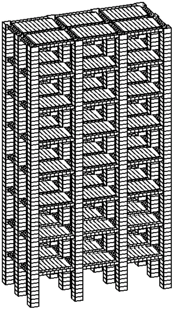
The invention relates to the technical field of constructional engineering, in particular to an integrated beam-slab-column formwork structural system and a construction method. The structural system is a frame structure formwork system composed of a non-dismantling column formwork, a beam formwork, a beam-column joint formwork and a slab formwork which are connected to each other; the column formwork, the beam-column joint formwork, the beam formwork and the slab formwork are respectively composed of corresponding formwork units by means of splicing; a non-dismantling formwork unit is made of a thin-wall shell structure and used as a formwork when pouring concrete, and also used as finishing material in the later stage, wherein one side of the non-dismantling formwork unit is processed into a rough surface and the other side is smooth; the splicing parts of the formwork units are built in by adopting a form of concave-convex groove and tongue; an outer side of the non-dismantling formwork is fastened by using a fastening hoop to resist the cast-in-situ concrete side pressure; the beam-column joint formwork makes the integrated beam-slab-column formwork structural system applicable to a preformed structural member, and also applicable to cast-in-situ; the preformed member is spliced or concrete is casted in situ to the preformed member to form one building unit of the frame structure, and a plurality of building units form a multilayer or a high-rise frame structure.
Description
technical field [0001] The invention relates to the technical field of construction engineering, in particular to a frame beam-slab-column formwork structure system and a construction process that apply an industrialization model to the field of building structures. Background technique [0002] The traditional construction sequence of the frame structure is to tie the steel bars-support the formwork-pour the concrete-remove the formwork. This process is not only labor-intensive and material-intensive, but also the construction is relatively complicated. The quality of the components is greatly affected when the formwork is removed. For decoration, the bond between the plaster layer and the concrete surface is not strong, and hollow cracks are easy to occur, which takes a long time and costs a lot. For large-scale steel formwork pouring, large-scale hoisting equipment must be used for its installation and removal, and the safety risk factor is high. The emergence of prefabri...
Claims
Login to View More Application Information
Patent Timeline
 Patent Type & AuthorityApplications(China)
IPC IPC(8): E04B1/16
Inventor王国富王威汐
OwnerJINAN RAILWAY TRANSPORT GRP CO LTD