Structure for improving air film cooling efficiency of downstream wall surface of slotted air film hole
An air film cooling and air film hole technology, which is applied to the supporting elements of blades, machines/engines, mechanical equipment, etc., can solve the problems of flow obstruction, and do not consider the superposition of air film cooling and cooling, so as to achieve improved coverage and enhanced coverage. Lateral cooling effect, simple structure effect
- Summary
- Abstract
- Description
- Claims
- Application Information
AI Technical Summary
Problems solved by technology
Method used
Image
Examples
Embodiment 1
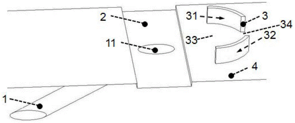
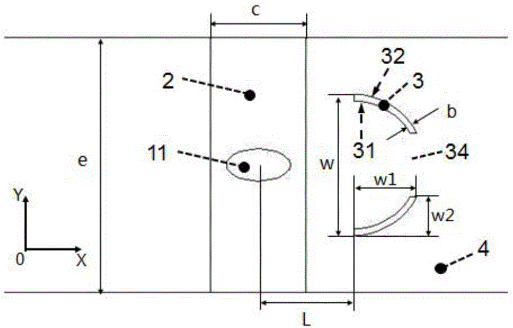
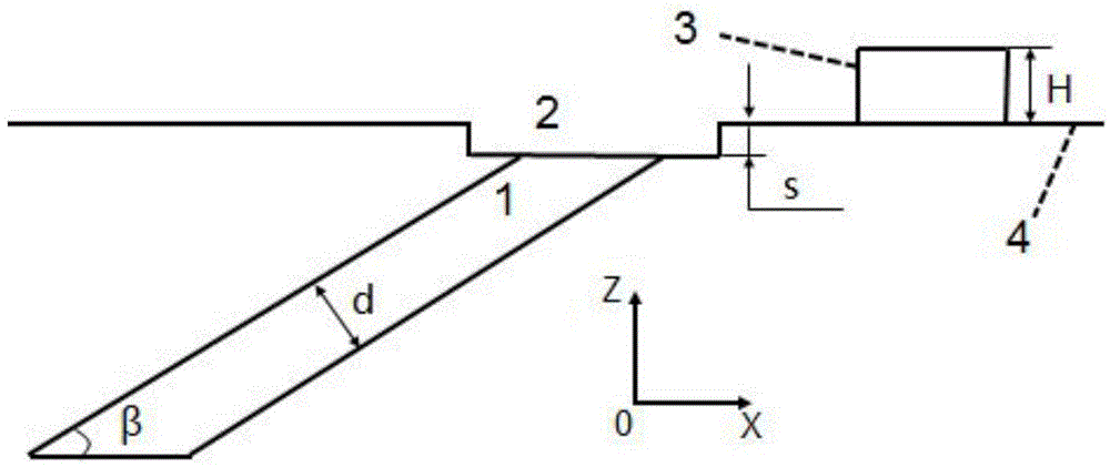
[0032] In this embodiment, the structure (see Figure 1-3 ) includes air film hole 1, transverse slot 2, protrusion 3 and wall surface 4, protrusion 3 is located in the downstream direction of wall surface 4, protrusion 3 is two semi-bracket-shaped circular arcs, and the two arcs pass through the air film hole The center of the outlet 11 and the straight line perpendicular to the wall 4 are axisymmetrically arranged. The direction of the protrusion 3 facing the air film hole 1 is the front part, the front part is the air inlet 33, and the opposite direction is the air outlet 34. The protrusion 3 The profile of the side facing away from the air film hole is the back pressure profile 32, the profile of the side facing the air film hole 1 is the windward profile 31, and the back pressure profile 32 and the windward profile 31 are arc lines. exist figure 2 and image 3 Among them, the three flow directions are represented by coordinates X, Y, and Z respectively, X is the flow d...
Embodiment 2
[0038] The position and connection relationship of each part in the described structure of this embodiment are the same as those in Embodiment 1. In this embodiment, the protrusion 3 is two spiral protrusions, and the two spiral protrusions are arranged axisymmetrically with the center of the outlet 11 of the air film hole and perpendicular to the wall 4, and the protrusion 3 faces the air film The direction of the hole 1 is the front, the front is the air inlet 33, and the opposite direction is the air outlet 34, and the side profile of the protrusion 3 facing away from the air film hole is the back pressure profile 32, facing the air film hole One side of 1 is the windward profile 31, the back pressure profile 32 is a spiral and protrudes downstream of the wall, the windward profile 31 is an arc line and protrudes downstream of the wall, the windward profile 31 and the back pressure The spacing of the molded lines 32 is adjustable, and the spacing gradually decreases from th...
Embodiment 3
[0041] The position and connection relationship of each part in the described structure of this embodiment are the same as those in Embodiment 1. Protrusion 3 is two prism type arcs in the present embodiment (referring to Figure 9 ), the two circular arcs are axisymmetrically arranged with the center of the air film hole outlet 11 and the straight line perpendicular to the wall surface 4, the direction of the protrusion 3 facing the air film hole 1 is the front, and the front is the air inlet 33, on the contrary The direction is the air outlet 34, the side profile of the protrusion 3 facing away from the air film hole is the back pressure profile 32, the side profile facing the air film hole 1 is the windward profile 31, and the back pressure profile 32 It is an arc protruding toward the downstream direction of the wall surface, the windward profiled line 31 is a straight line, and the distance between the windward profiled line 31 and the backpressure profiled line 32 is a v...
PUM
 Abstract
Description
Claims
Application Information
 - R&D
- Intellectual Property
- Life Sciences
- Materials
- Tech Scout
- Unparalleled Data Quality
- Higher Quality Content
- 60% Fewer Hallucinations
Browse by: Latest US Patents, China's latest patents, Technical Efficacy Thesaurus, Application Domain, Technology Topic, Popular Technical Reports.
© 2025 PatSnap. All rights reserved.Legal|Privacy policy|Modern Slavery Act Transparency Statement|Sitemap|About US| Contact US: help@patsnap.com


