Friction difference brake method

A technology of friction and friction parts, which is applied in the field of mechanical transmission or braking, can solve the problems of complex control and transmission devices, and achieve the effects of simple structure, wide application range and improved braking accuracy.

Inactive Publication Date: 2015-05-06
韩树海
View PDF4 Cites 2 Cited by
  • Summary
  • Abstract
  • Description
  • Claims
  • Application Information

AI Technical Summary

Problems solved by technology

That is, the braking force of almost all brakes requires a mechanical, hydraulic or pneumatic power system to provide braking energy, which leads to more complicated control and transmission devices

Method used


Image

  • Friction difference brake method
  • Friction difference brake method
  • Friction difference brake method

Examples


Embodiment 1

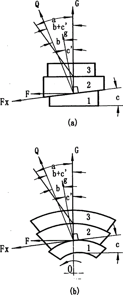
[0063] Figure 5 It is a schematic diagram of the friction type linear one-way brake of the present invention: the braking direction is the direction of the reverse driving force angle; the three elements of friction include the driving force part, the friction part and the target part; The moving direction is installed in the frame (brake caliper) in turn; the frame is fixed on the equipment and floats perpendicular to the braking direction; the target part is located between the side of the friction part and the frame; the driving part and the friction part The contact surface is an inclined surface, which is in a constant contact state; the contact surface between the friction part and the target part is a plane; the friction coefficient between the friction part and the target part is generally more than 1 times that between the friction part and the driving part ; b+c≤a or 90°>b+c>a and it is a certain value; where a is the friction angle between the friction part and the...

Embodiment 2

[0067] Figure 6 It is a schematic diagram of a friction-type linear one-way brake outsourcing type 3 (guide rail): the braking direction is the direction of the reverse driving force angle; the three elements of friction include the driving force component, the friction component and the target component; Installed on the frame (not shown), the friction part is installed against the driving part; the frame is fixed on the equipment and floats perpendicular to the braking direction; the two wings of the target part are located on both sides of the driving part and the friction part; The contact surface between the driving force part and the friction part is a slope, which is in a constant contact state; the contact surface between the driving part, the friction part and the target part is a plane; the friction coefficient between the friction part and the target part is generally greater than that between the friction part and the target part. The friction coefficient between ...

Embodiment 3

[0070] Figure 7 It is a schematic diagram of a friction-type linear bidirectional brake capable of split-directional control in the present invention: it is equal to the embodiment 1 Figure 5 The two one-way friction self-locking devices shown are opposite and reversely combined; the frame (brake caliper) 8 floats perpendicular to the braking direction; three working conditions can be realized through the control of their respective controllers 7: 1) one-sided During work, action process is the same as embodiment one Figure 5 As shown, at this moment, the friction part 2 on the other side is rigidly constrained by the frame, thereby clamping the target part; when the reverse movement, the part 2 on the working side is in an unlocked sliding state, and the part 2 on the other side is restricted by the controller 7 And will not produce action - this is a one-way braking condition. 2) Both sides work at the same time——when both controllers 7 are released, both directions are...


PUM


Abstract

The invention relates to a friction difference brake method. Friction difference three element parts are adopted for mechanical brake including linear brake and rotation brake, the friction difference three element parts comprise a drive part, a friction difference part and a target part, the friction difference part is connected with the drive part or a rack through an elasticity keeping part and a brake controller, the drive part is fixedly installed on the rack, and the friction difference part is installed on the drive part in a floating mode. The friction coefficient between the friction difference part and the target part is larger than that between the friction difference part and the drive part by over one time, and a sliding or rolling friction mode is adopted between the drive part and the friction difference part. When b+c <=a, the friction difference self-locking brake is in a complete brake form; when 90 degrees >b+c >a and b+c is a definite value, the friction difference self-locking brake is in a definite proportion speed reduction brake form; when 90 degrees >b+c >=a and b+c is adjusted randomly within the range, wherein a is the friction angle between the friction difference part and the target part, b is the friction angle between the friction difference part and the drive part, c is the drive angle, b+c is a friction difference angle, the friction difference self-locking brake is in a whole journey brake form.

Description

technical field [0001] The invention belongs to the field of mechanical transmission or braking. Background technique [0002] Braking is the process of stopping the existing motion of mechanical equipment and components in operation. Both electrical braking and mechanical braking are braking methods. Electrical braking is to achieve the effect of accelerating and stopping the equipment through the electrical connection mode opposite to the operation mode that drives the equipment to move; mechanical braking is to restrain the equipment through physical and mechanical methods. The existing movement of the device. [0003] Comparison of advantages and disadvantages: [0004] The most widely used is the friction mechanical brake. But almost all friction mechanical braking systems have four basic components. 1. Energy supply device: including various components that supply and adjust the energy required for braking and improve the state of the energy transfer medium. 2. Co...

Claims


Application Information

Patent Timeline
Patent Type & Authority Applications(China)
IPC IPC(8): F16D63/00
Inventor 韩树海
Owner 韩树海
Why Eureka
Try Eureka