Method for correcting elasticity modulus and stress-strain curve in metal material compression test

A compressive elastic modulus and strain curve technology, applied in the direction of applying stable tension/pressure to test the strength of materials, etc., can solve the problems of wrong compressive elastic modulus and too large difference between the nominal values ​​of compressive elastic modulus.

Active Publication Date: 2015-05-06
INST OF MECHANICS - CHINESE ACAD OF SCI
View PDF19 Cites 41 Cited by
  • Summary
  • Abstract
  • Description
  • Claims
  • Application Information

AI Technical Summary

Problems solved by technology

[0011] However, the most thorny problem encountered at present is: the cylindrical sample composed of L=(1~2)d and L=(2.5~3.5)d and the cylinder sample of L=(1~2)b and L=(2.5~ 3.5) The difference between the compressive ela

Method used


Image

  • Method for correcting elasticity modulus and stress-strain curve in metal material compression test
  • Method for correcting elasticity modulus and stress-strain curve in metal material compression test
  • Method for correcting elasticity modulus and stress-strain curve in metal material compression test

Examples


Embodiment 1

[0070] Preferred embodiments of the present invention are described in detail below in conjunction with accompanying drawing:

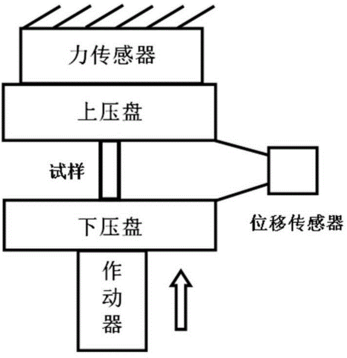
[0071] (1) Place the sample between the upper and lower pressure plates, and install a displacement sensor between the upper and lower pressure plates to measure the displacement between the upper and lower pressure plates as the compression deformation of the sample, such as figure 1 shown. This test method can ensure that the measured deformation is the compression deformation of the sample, and because the displacement sensor is located on the side of the upper and lower pressure plates, it will not be crushed by the pressure plate due to the accidental sudden break of the sample, which is relatively safe.

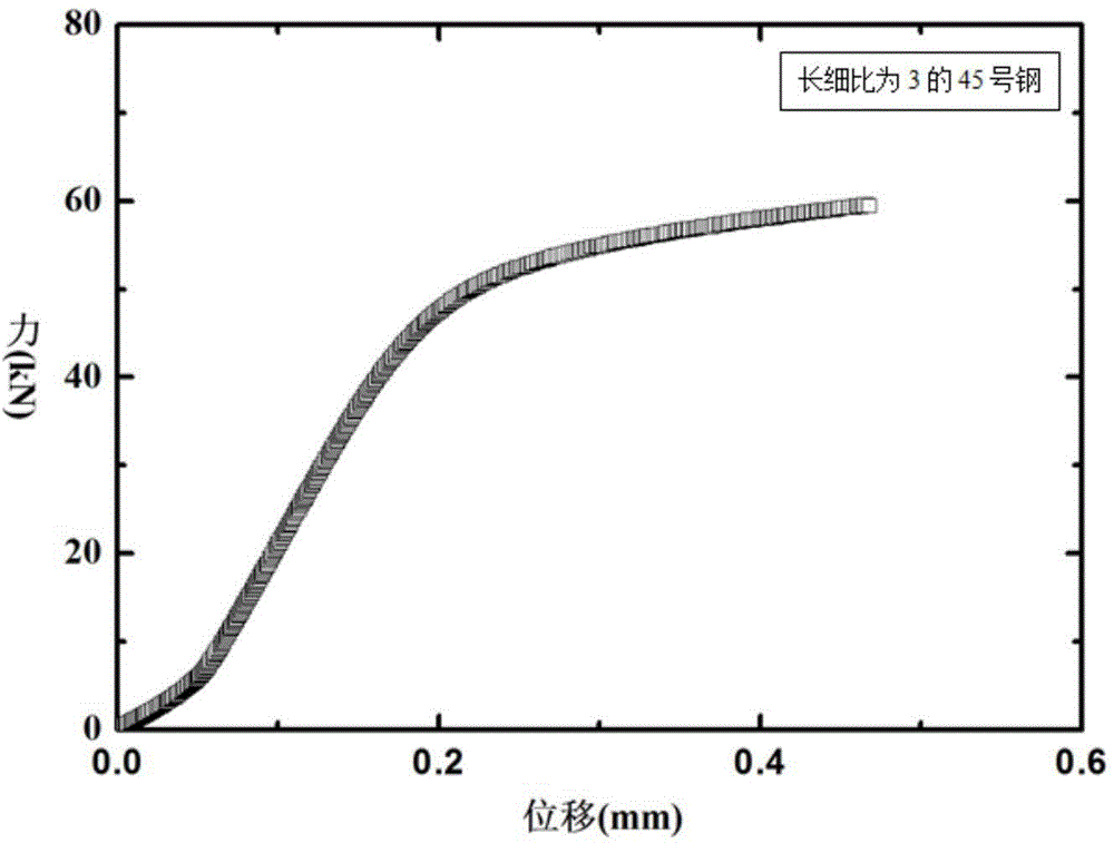
[0072] The sample used here is No. 45 steel with an aspect ratio of 3, a diameter of 10 mm, and a height of 30 mm. The displacement sensor used here is a strain gauge displacement sensor. Non-contact displacement sensors such as laser or vid...

Embodiment 2

[0090] The sample used here is 304 steel with an aspect ratio of 2, a diameter of 10mm, and a height of 20mm. The steps are the same as in Example 1, but in step (5), change formula (3) to formula (4), and the correction process is the same as the correction process of β of the sample whose slenderness ratio is 3 in the specification. For comparison of stress-strain curves before and after correction, see Figure 5 .

[0091] β = 0.26 m = 0.26 E P E S - - - ( 4 )

[0092] In this embodiment, the modulus of the 304 steel national standard size sample with a slenderness ratio of 2 is 78.1 GPa measured by the compression test, which is very different from the nominal value of 188.6 GPa (error 58.6%).

[0093] After being corrected by the met...


PUM

PropertyMeasurementUnit
Compressive modulus of elasticityaaaaaaaaaa
Modulusaaaaaaaaaa
Compressive modulus of elasticityaaaaaaaaaa

Abstract

The invention relates to a method for correcting an elasticity modulus and stress-strain curve in a metal material compression test and a related model. The model is a sandwiched model. According to the method for correcting a metal material compression elasticity modulus and stress-strain curve obtained by the model, most of national standard or non-national standard samples of metal materials with linear strengthening behaviors, particularly metal samples in which L is equal to (2.5-3.5) d or L is equal to (2.5-3.5) b or L is equal to 2d or L is equal to 2b can be corrected, so that the real compression elasticity modulus can be measured on samples which are unsuitable for measuring the compression elasticity modulus in the national standard stipulation; particularly, the method can be used for correcting the elasticity modulus and stress-strain curve of small-size non-national standard samples. According to the method, the construction of a mechanical constitutive equation is greatly convenient, and for research and development of novel materials, the requirements of the test technology on the sizes and shapes of the samples can be lowered, the measured mechanical parameters are reliable, and the research and development period is shortened.

Description

technical field [0001] The invention relates to the field of detection of mechanical properties of materials, in particular to a method for correcting elastic modulus and stress-strain curves in metal material compression tests and related models. Background technique [0002] Uniaxial compression test is one of the general methods to test the mechanical properties of metal materials. It has the advantages of simple test method and clear physical meaning of the test results. It is widely used in engineering design and research on the mechanical properties of materials. [0003] The current national standard "GB / T 7314-2005 Compression Test Method for Metal Materials at Room Temperature" stipulates that the diameter d=10mm~20mm must be met for cylindrical samples, and b=10mm~20mm must be met for cylindrical samples with square cross-sections. Among them, for the cylindrical sample of L=(1~2)d and the cylindrical sample of square section of L=(1~2)b, it is only applicable to t...

Claims


Application Information

Patent Timeline
IPC IPC(8): G01N3/08
Inventor 郇勇刘薇董杰代玉静朱静静
Owner INST OF MECHANICS - CHINESE ACAD OF SCI
Why Eureka
Try Eureka