Floating Canal Water Velocity Meter

A flow velocity measurement, floating technology, applied in the direction of fluid velocity measurement, velocity/acceleration/shock measurement, measuring devices, etc., can solve the problems of reliability discount, inconvenient installation and use, troublesome installation and maintenance, etc., to achieve the goal of reducing wind force impact, simple and practical structure, good reliability

Inactive Publication Date: 2017-11-14
游巍亭
View PDF7 Cites 1 Cited by
  • Summary
  • Abstract
  • Description
  • Claims
  • Application Information

AI Technical Summary

Problems solved by technology

The flow rate sensor is installed on the support mechanism. The first support mechanism in the prior art has a vertical pole type (or measuring pole type). This installation method is simple, but it is not suitable for deep water areas, and installation and maintenance are troublesome; The second type uses steel wire ropes to suspend lead fish counterweights. The support mechanism of this method is bulky and bulky, which is inconvenient to install and use. It can only be installed and used near the river bank, and cannot measure the water speed in the center of the river.
In addition, the canal water flow velocity measuring instrument in the prior art needs to use a very long wire to connect the flow velocity sensor with the flow velocity measuring instrument on the river bank. will be greatly discounted

Method used


Image

  • Floating Canal Water Velocity Meter
  • Floating Canal Water Velocity Meter

Examples


Embodiment Construction

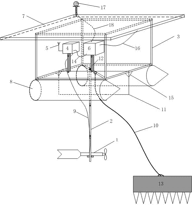
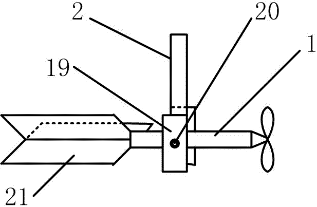
[0012] exist figure 1 Among them, the signal input end of the flow rate sensor 1 and the flow rate calculation system 4 is electrically connected through the signal line 9 (when the sensor is a reed switch, the signal line 9 is a double line), the flow rate sensor 1 is installed at the lower end of the support rod 2, and the support rod The upper end of 2 and frame 3 are mutually fixed. The support rod 2 is composed of multi-section stainless steel pipe ends socketed together with fastening screws, so as to change the total length to meet the needs of different test water depths. The frame 3 is welded by a stainless steel metal square tube, and a reinforced metal strip of the same material can be added at the bottom to facilitate the installation of parts such as the pole 2. Two buoys 8 made of stainless steel are installed at the bottom of the frame 3 . The buoy 8 is elongated along the downstream direction, and the upstream direction is made into a pointed shape. This can...


PUM


Abstract

The invention discloses a floating type river and canal water flow velocity measuring instrument. A flow velocity sensor 1 is electrically connected with the signal input end of a flow velocity measuring and computing system 4 through a signal line 9 and is mounted at the lower end of a supporting rod 2, the upper end of the supporting rod 2 is fixed to a frame 3, float bowls 8 and a downstream plate 11 are mounted at the bottom of the frame 3, the bottom of the frame 3 is connected with the upper end of a positioning rope 10, and the lower end of the positioning rope 10 is connected with a positioning anchor 13. The floating type river and canal water flow velocity measuring instrument has the advantages that time-consuming and labor-consuming complex construction-type mounting in the prior art is changed into throwing-type mounting, and the instrument is not limited to be mounted on the shore and can be thrown in the center on a river conveniently, so that water flow velocity measuring precision is improved, testing location change is flexible and convenient and mounting use cost is reduced; the floating type river and canal water flow velocity measuring instrument is applicable to being connected into a water level monitoring system based on Internet of Things.

Description

technical field [0001] The invention relates to a liquid flow rate measuring instrument, in particular to a floating river channel water flow rate measuring instrument. Background technique [0002] The measurement of water flow velocity in rivers and canals is an important test content for water conservancy, factories and mines, environmental monitoring, hydrogeological survey, agriculture and other departments to monitor and manage the environment. Existing water flow velocity measuring instruments in contact with river water include propeller type and rotary cup type according to the difference of water velocity sensors, but the mainstream is still the propeller type. The physical principle of the propeller type flow rate sensor is: the water pushes the propeller blades to rotate, and the rotation of the propeller blades drives the rotor to rotate through the connection mechanism, which drives the two magnets on the rotor to rotate. When the magnets turn close to the reed...

Claims


Application Information

Patent Timeline
Patent Type & Authority Patents(China)
IPC IPC(8): G01P5/00
Inventor 游巍亭张长军郑仕强赵伟黄振离姚广华靳永强陶新红袁诚闫军召田海洋王冰司文青黄素琴常喜兰张天琪游斐斐
Owner 游巍亭
Why Eureka
Try Eureka