Transmultiplexer and display device

A technology of multiplexing and converting

Inactive Publication Date: 2015-05-06
BOE TECH GRP CO LTD +1
View PDF5 Cites 12 Cited by
  • Summary
  • Abstract
  • Description
  • Claims
  • Application Information

AI Technical Summary

Problems solved by technology

When the ambient temperature rises, the power consumption of the display panel w

Method used


Image

  • Transmultiplexer and display device
  • Transmultiplexer and display device
  • Transmultiplexer and display device

Examples


Embodiment Construction

[0024] The following will clearly and completely describe the technical solutions in the embodiments of the present invention with reference to the accompanying drawings in the embodiments of the present invention. Obviously, the described embodiments are only some, not all, embodiments of the present invention.

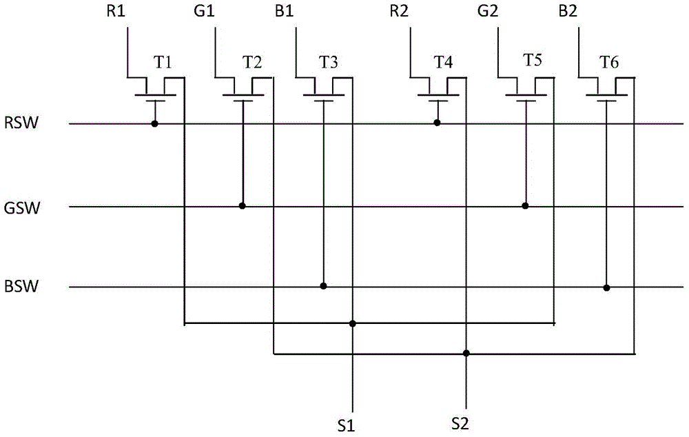
[0025] Such as figure 1 Shown is a schematic structural diagram of a multiplexing converter. After the signal lines R1, G1, B1, R2, G2, and B2 are controlled by multiplexing converters, only two signal lines S1, S2 are needed to realize the input. Among them, RSW, GSW, and BSW are three control signals of the multiplexing converter, which are used to time-divisionally turn on the thin film transistors (T1~T6) in the multiplexing converter to realize multiplexing of signal lines S1 and S2. reuse.

[0026] The inventor found through research that this multiplexing converter has a high operating frequency and strong charge transmission capability (that is, a large swi...


PUM


Abstract

An embodiment of the invention discloses a transmultiplexer and a display device, and relates to the field of display. By the transmultiplexer and the display device, the problems of insufficient drive and abnormal display both caused by transmultiplexers can be solved. The transmultiplexer comprises a plurality of thin film transistors. Control signal generation units are serially connected between the control signal input ends of the transmultiplexer and the control ends of the thin film transistors, and are used for generating control signals under the control of signals input by the control signal input ends, wherein the control signals are used for controlling on/off of the thin film transistors to achieve signal line multiplexing.

Description

technical field [0001] The invention relates to the field of display, in particular to a multiplexing converter and a display device. Background technique [0002] With the improvement of display panel resolution, the bottleneck of power consumption becomes more and more prominent in mobile display products. When the ambient temperature rises, the power consumption of the display panel will increase sharply, and the display panel often has insufficient drive. [0003] A multiplexer (MUX), also known as a multiplexer, is a device that packs multiple transport streams into one transport stream for input and output during data transmission. In high-resolution display products, a multiplexing converter (MUX) is usually placed in the PAD area of ​​the display panel to reduce the number of driving signal lines and reduce the cost of signal driving chips (driver ICs). Contents of the invention [0004] Embodiments of the present invention provide a multiplexing converter and a ...

Claims


Application Information

Patent Timeline
IPC IPC(8): G09G3/20
Inventor 辛燕霞朴承翊蒋学莫再隆
Owner BOE TECH GRP CO LTD
Why Eureka
Try Eureka