Vibration power generator

A vibration generator and magnetic vibration technology, applied in electrical components, electromechanical devices, etc., can solve problems such as the inability to use vibration energy or inertial energy, and the limitation of placement methods.

Active Publication Date: 2015-05-06
QUANZHOU NORMAL UNIV
View PDF7 Cites 3 Cited by
  • Summary
  • Abstract
  • Description
  • Claims
  • Application Information

AI Technical Summary

Problems solved by technology

[0007] Because these vibrating generators change the magnetic flux of the coil through the up and down vibration of the magnet to achieve the purpose of generating electricity, there are two problems as follows: 1. The traditional vibrating generator can only use the vibration energy of vertical motion and cannot use the vibration energy in the horizontal direction. And other vibration energy or inertial energy in any direction; 2. In order to obtain the vibration energy of vertical vibration, the placement of traditional vibration generators is also limited, and it must be placed vertically to ensure that the magnon can move up and down in the vertical direction vibration

Method used


Image

  • Vibration power generator
  • Vibration power generator
  • Vibration power generator

Examples


Embodiment 1

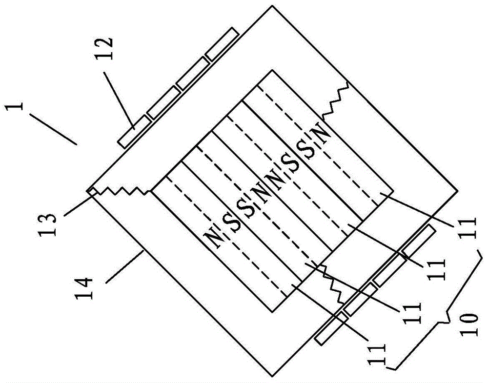
[0042] Such as Figures 1 to 8As shown, in this embodiment, a plurality of magnetic strips 11 are used to form an integrated magnon 10 , and each magnetic strip 11 is in the shape of a parallelepiped, so that a regular cube is formed to facilitate three-point positioning and suspension. A plurality of magnetic strips 11 are arranged side by side with opposite poles, with N poles facing N poles, S poles facing S poles, and the same poles facing each other can increase the change of the magnetic flux of the coil to the greatest extent. Each magnetic strip 11 is wound with a set of independent coils 12 respectively, the magnetic pole arrangement direction of the magnon 11 is perpendicular to the winding direction of the coil 12, and the winding width of each independent coil 12 is not larger than that of a single magnetic strip 11 in the vertical coil 12. The width in the winding direction.

Embodiment 2

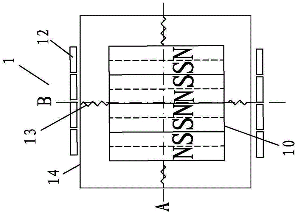
[0044] Such as figure 1 As shown, in this embodiment, the magnon 10 is suspended in a housing 14 matching its shape by at least three springs 13 in a three-point positioning manner, and the housing 14 is made of non-magnetic material. When the magnon 10 is under the action of an external force in any direction, the magnon 10 will vibrate in any direction accordingly, and the vibration will cause the magnetic flux of the coil 12 to change, thereby generating a current, and electrically connecting the corresponding output ends of the coil 12 to external components , to provide power to external components.

Embodiment 3

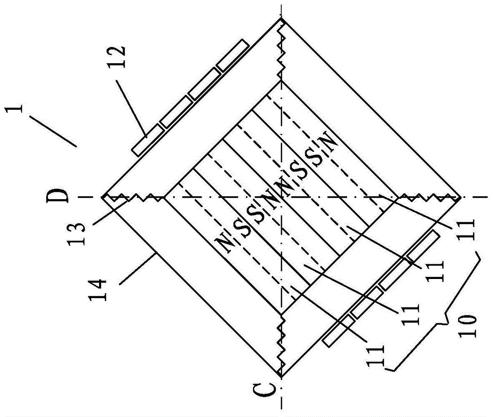
[0046] Such as figure 2 As shown, in this embodiment, the magnon 10 is suspended by four springs 13 along two intersection lines A and B or two diagonal lines C and D perpendicular to each other on at least one plane. Inside the coil 12. Connecting and suspending positioning on the diagonal through the spring 13 will have a better suspension positioning effect.

[0047] When each magnetic strip 11 is a regular shape, such as a parallelepiped, and the magnon 10 also forms a parallelepiped, then the two perpendicular intersection lines A and B or the two diagonal lines C and D are the symmetry lines of the magnon 10 respectively. , so that it is convenient to suspend the magnon 10 inside the casing 14 , and it is also convenient to wind the coil 12 outside the casing 14 .


PUM


Abstract

The invention discloses a vibration power generator comprising a magnon and a coil winded on the magnon. The magnon is suspended in the coil in a three-point positioning manner through springs, the magnetic flux of the coil can be changed through the magnon along the vibration produced in optional direction, and current is produced accordingly. The vibration power generator further comprises a plurality of magnetic resonance units adopting the structures, and the magnetic resonance units are connected through the springs, and the magnons are suspended in the corresponded coils through springs through at least three formed spring connection points. The magnons are capable of vibrating in optional directions, the vibration energy of the optional directions can be collected, the magnetic flux of the external coil is changed according to the vibration, and the vibration is converted into power by the electro-magnetic principle; the arrangement direction limitation is avoided, and the vibration power generator has the promised application prospect in the fields of mobile communication equipment such as mobile phones and tablet computers and electrical vehicles.

Description

technical field [0001] The present invention relates to a vibration generator, in particular to the arrangement structure of the magnetic vibrator in the vibration generator. Background technique [0002] With the escalation of the nuclear energy crisis and the continuous depletion of non-renewable resources such as oil and coal, the development of new energy sources has become one of the biggest challenges facing mankind in the new century. In order to realize the sustainable development of human society, scientists have proposed the technology of making the most use of resources and energy and the technology of least burden on the environment—committed to the development of clean and efficient renewable energy, as well as new technologies and new equipment for energy storage and conversion . [0003] In the new upsurge of finding new energy sources, renewable energy sources such as wind energy, solar energy and geothermal energy are gradually appearing before people's eye...

Claims


Application Information

Patent Timeline
Patent Type & Authority Applications(China)
IPC IPC(8): H02K35/02
Inventor 吴允苗朱君秋
Owner QUANZHOU NORMAL UNIV
Why Eureka
Try Eureka