Check patentability & draft patents in minutes with Patsnap Eureka AI!

High-voltage DC power-taking circuit

A DC power-taking, high-voltage technology, applied in the direction of DC network circuit devices, circuit devices, electrical components, etc., can solve the problems that cannot meet the design requirements of the unit converter

Active Publication Date: 2017-12-29
BEIJING ETECHWIN ELECTRIC
View PDF8 Cites 0 Cited by
  • Summary
  • Abstract
  • Description
  • Claims
  • Application Information

AI Technical Summary

Problems solved by technology

[0003] For the high-voltage system of the converter in the unit, its normal working voltage is usually higher than 1000V, so the existing circuit topology cannot meet the design requirements of the unit converter

Method used


Image

  • High-voltage DC power-taking circuit
  • High-voltage DC power-taking circuit
  • High-voltage DC power-taking circuit

Examples


Embodiment 1

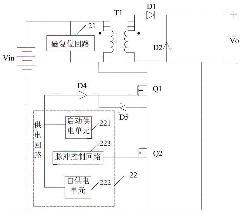
[0041] figure 2 A schematic diagram of the circuit structure of the high-voltage DC power-taking circuit provided by the present invention, the circuit can realize high-voltage power-taking on the DC bus of the wind power generating set and convert it into the voltage required by the unit controller. Such as figure 2 As shown, the high-voltage DC power-taking circuit specifically includes:

[0042] High-frequency isolation transformer T1, power supply circuit 22, output rectifier diode D1, freewheeling diode D2, magnetic reset circuit 21, first MOS transistor Q1 and second MOS transistor Q2 connected in series in sequence;

[0043] The magnetic reset circuit 21 is connected in parallel on the primary side of the high-frequency isolation transformer T1; the high-voltage end of the primary side of the high-frequency isolation transformer T1 is figure 2 The high-voltage terminal of the input terminal of the high-voltage DC power-taking circuit shown; the source of the second...


PUM


Abstract

The embodiment of the invention provides a high-voltage DC power supply circuit. The high-voltage DC power supply circuit comprises a high-frequency isolation transformer, a power supply circuit, an output rectification diode, a freewheel diode, a magnetic reset circuit, a first MOS (metal oxide semiconductor) transistor and a second MOS transistor, wherein the magnetic reset circuit, the first MOS transistor and the second MOS transistor are sequentially connected in series; the magnetic reset circuit is connected in parallel to the primary side of the high-frequency isolation transformer; the high-voltage end of the primary side of the high-frequency isolation transformer serves as the high-voltage end of the input end of the high-voltage DC power supply circuit; the source electrode of the second MOS transistor is the low-voltage end of the input end of the high-voltage DC power supply circuit; the power supply circuit is connected with the first MOS transistor and the second MOS transistor for providing driving pulse to the first MOS transistor and the second MOS transistor; the secondary side of the high-frequency isolation transformer is connected with the output rectification diode and the freewheel diode; both ends of the freewheel diode are the voltage output ends of the high-voltage DC power supply circuit. The high-voltage DC power supply circuit enables a circuit system to be stable during high-voltage power supply.

Description

technical field [0001] The invention relates to the technical field of power electronics, in particular to a high-voltage DC power-taking circuit. Background technique [0002] With the continuous improvement of the design level of converters in wind turbines (referred to as "units"), it has gradually become a trend in the development of power supply for the control system in the unit to take power from the DC bus to supply power to the control system in the unit. Conventional DC / DC switching power supplies have high withstand voltage requirements for power devices, and the input voltage range is relatively narrow. The corresponding conventional circuit topologies such as single-ended forward circuits and power devices are mostly used in working environments below 100V. At present, most of the research on high-voltage DC power acquisition at home and abroad is aimed at the converter system with the DC bus voltage below 1000V. [0003] As for the high-voltage system of the c...

Claims


Application Information

Patent Timeline
Patent Type & Authority Patents(China)
IPC IPC(8): H02M1/088
CPCH02J1/00H02M1/088
Inventor 孔令冲张群孟昭鹤
Owner BEIJING ETECHWIN ELECTRIC
Features
  • R&D
  • Intellectual Property
  • Life Sciences
  • Materials
  • Tech Scout
  • Unparalleled Data Quality
  • Higher Quality Content
  • 60% Fewer Hallucinations
Learn More