Frequency multiplier based on delayed phase-locked loop structure

A phase-locked loop and frequency multiplier technology is applied in the field of frequency multipliers based on a delay phase-locked loop structure, which can solve the problems of increasing the hardware cost of a clock generator and achieve the effect of small hardware cost

Active Publication Date: 2015-05-06
PEKING UNIV
View PDF5 Cites 6 Cited by
  • Summary
  • Abstract
  • Description
  • Claims
  • Application Information

AI Technical Summary

Problems solved by technology

This will greatly increase the hardware cost of the clock generator based on the DLL structure

Method used


Image

  • Frequency multiplier based on delayed phase-locked loop structure
  • Frequency multiplier based on delayed phase-locked loop structure
  • Frequency multiplier based on delayed phase-locked loop structure

Examples


Embodiment Construction

[0018] In order to make the purpose, technical solutions and advantages of the embodiments of the present invention clearer, the technical solutions in the embodiments of the present invention will be clearly described below in conjunction with the accompanying drawings in the embodiments of the present invention. Obviously, the described embodiments are the Some, but not all, embodiments are invented. Based on the embodiments of the present invention, all other embodiments obtained by persons of ordinary skill in the art without making creative efforts belong to the protection scope of the present invention.

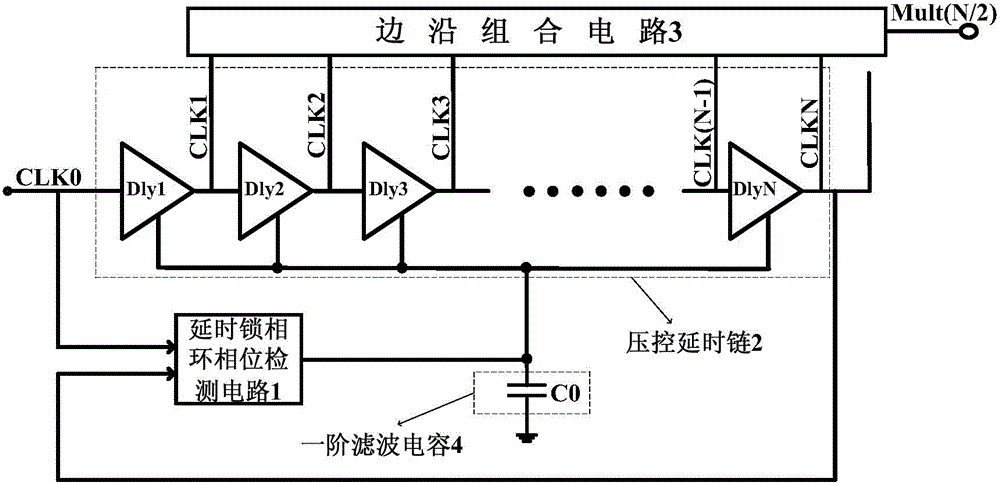
[0019] Such as figure 1 As shown, this embodiment discloses a frequency multiplier based on a delay phase-locked loop structure, including:

[0020] Delay phase-locked loop phase detection circuit 1, voltage-controlled delay chain 2, edge combination circuit 3 and first-order filter capacitor 4;

[0021] Wherein, the input signal of the delay phase-locked loop phase d...


PUM


Abstract

The invention discloses a frequency multiplier based on a delayed phase-locked loop structure. The frequency multiplier based on the delayed phase-locked loop structure can solve the problem that the implementation cost of the existing frequency multiplication technical hardware based on the delayed phase-locked loop structure is too large. The frequency multiplier comprises a delayed phase-locked phase detection circuit, a voltage-controlled delay chain and an edge combination circuit, wherein the delayed phase-locked phase detection circuit is used for detecting the phase relationship between the input reference lock signal CLK0 and the output feedback clock signal CLKN of the voltage-controlled delay chain and generating the control voltage Vc which adjusts the delay of the voltage-controlled delay chain. The voltage-controlled delay chain comprises multiple delay units which are used for generating multiple multi-phase clock signals with equal phase differences. The edge combination circuit is composed of multiple frequency multiplier circuits and a two frequency-dividing circuit, wherein the multiple frequency multiplier circuits are used of conducting edge combination on multiple clock signals with equal phases so as to obtain a multiple frequency multiplication output signals, the two frequency-dividing circuit is used for conducting frequency-dividing operation on the multiple frequency multiplication output signals to obtain frequency multiplication out signals whose duty ratio is 50% (N/2).

Description

technical field [0001] The present invention relates to the technical field of frequency multiplier design based on a delay locked loop (Delay Locked Loop, DLL) structure, in particular to a frequency multiplier based on a delay locked loop structure. Background technique [0002] There is an increasing need for on-chip clock multipliers in high-speed consumer electronics. With the continuous improvement of the speed and performance of large-scale integrated circuit systems, the requirements for suppressing clock skew and jitter are getting higher and higher. However, reducing clock skew and jitter becomes more difficult as clock frequency and circuit integration levels increase, whether the jitter is internal or from substrate or power supply noise. Generally, a phase-locked loop (Phase Locked Loop, PLL) and a DLL are used in microprocessors, memory interfaces, and communication chips to generate on-chip clocks. [0003] Among them, PLL is a high-level system with complex...

Claims


Application Information

Patent Timeline
Patent Type & Authority Applications(China)
IPC IPC(8): H03B19/00H03L7/16
Inventor 王源刘跃全贾嵩张兴
Owner PEKING UNIV
Why Eureka
Try Eureka