System and method for positioning PON network optical fiber link failures

A fiber optic link and fault location technology, which is applied in transmission systems, digital transmission systems, data exchange networks, etc., can solve problems such as increasing costs, achieve the effects of saving construction costs, ensuring normal transmission, and overcoming capacity insufficiency

Inactive Publication Date: 2015-05-06
苏州萤石光电科技有限公司
View PDF6 Cites 23 Cited by
  • Summary
  • Abstract
  • Description
  • Claims
  • Application Information

AI Technical Summary

Problems solved by technology

However, the introduction of the fiber optic reflector will not only increase the cost (installation engineering of the device itself), but also cause a new point of failure (the fiber optic reflector itself); at the same time, in

Method used


Image

  • System and method for positioning PON network optical fiber link failures
  • System and method for positioning PON network optical fiber link failures
  • System and method for positioning PON network optical fiber link failures

Examples


Embodiment Construction

[0044] The specific implementation manners of the present invention will be further described below in conjunction with the drawings and examples. The following examples are only used to illustrate the technical solution of the present invention more clearly, but not to limit the protection scope of the present invention.

[0045] The technical scheme of concrete implementation of the present invention is:

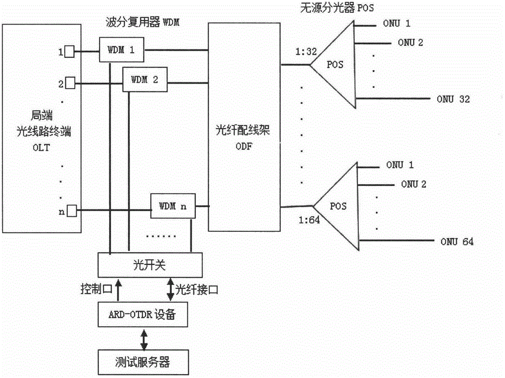
[0046] Such as figure 2 , image 3 As shown, the present invention provides a kind of PON network optical fiber link fault localization system, comprises all being arranged at central office: test server, ARD-OTDR equipment, optical switch, wavelength division multiplexer (WDM);

[0047] Described test server is connected with ARD-OTDR equipment by Ethernet;

[0048] The ARD-OTDR equipment is sequentially connected to the PON of one or more OLTs through an optical switch and a wavelength division multiplexer, and the test light is coupled to the backbone optical fiber;...


PUM


Abstract

The invention discloses a system for positioning PON (Passive Optical Network) network optical fiber link failures and a method for positioning PON network optical fiber link failures; the system comprises a testing server, an ARD-OTDR device, an optical switch and a wavelength division multiplexer all which are arranged on the local end, wherein the testing server is connected with the ARD-OTDR device through an Ethernet network; the ARD-OTDR device is connected with the PON of one or multiple optical line terminals (OLT) sequentially through the optical switch and the wavelength division multiplexer so that testing lights are coupled to a main optical fiber; the wavelength division multiplexer is arranged on the OLT optical fiber on the local end, the optical fiber passes through the wavelength division multiplexer and is connected with an optical fiber distribution frame, and the optical fiber of the optical fiber distribution frame is connected with the ONU(Optical Network Unit) of the user terminal through a passive optical splitter; under the same passive optical splitter, and the difference value among the optical fiber lengths of the different users is no less than 1m. According to the method and the system, PON network optical fiber link failures can be positioned.

Description

technical field [0001] The invention relates to a PON network optical fiber link fault location system and location method. Background technique [0002] Passive Optical Network PON (Passive Optical Network) is a point-to-multipoint structure, and its typical networking structure is as follows: figure 1 shown. PON is composed of an OLT (Optical Line Terminal) at the central office, an ONU (Optical Network Unit) at the user end, and an ODN (Optical Distribution Network). It is a single-fiber bidirectional system. In the downstream direction (OLT to ONU), the signal sent by the OLT reaches each ONU through the ODN; in the upstream direction (ONU to OLT), each ONU sends a signal to the OLT at a specified time. ODN consists of optical cables / optical fibers and passive optical devices such as POS (Passive Optical Splitter), providing optical channels between OLT and ONU. PON has become the main implementation form of FTTX due to its advantages of high bandwidth, multi-service ...

Claims


Application Information

Patent Timeline
IPC IPC(8): H04B10/071H04L12/24
Inventor 周荣海
Owner 苏州萤石光电科技有限公司
Why Eureka
Try Eureka