Vehicle brake apparatus

A technology of braking device and vehicle, applied in the direction of braking action starting device, brake, braking component, etc. The effect of dynamic operation feeling and good braking operation feeling

Inactive Publication Date: 2015-05-06
TOYOTA JIDOSHA KK
View PDF8 Cites 5 Cited by
  • Summary
  • Abstract
  • Description
  • Claims
  • Application Information

AI Technical Summary

Problems solved by technology

As a result, the driver (passenger) is likely to perceive the operation sound accompanying the operation of the electromagnetic on-off valve, which may impair the good brake operation feeling.
[0009] In addition, in the above-mentioned conventional brake system, it is necessary to open and close the holding valve and the pressure reducing valve in response to the operation of the driver in the return direction until the brake pedal is released, and it is difficult to adjust the hydraulic pressure of the wheel cylinder. rapid decompression
As a result, there is a possibility that the driver feels a sense of dissonance with the brake operation

Method used


Image

  • Vehicle brake apparatus
  • Vehicle brake apparatus
  • Vehicle brake apparatus

Examples


Embodiment Construction

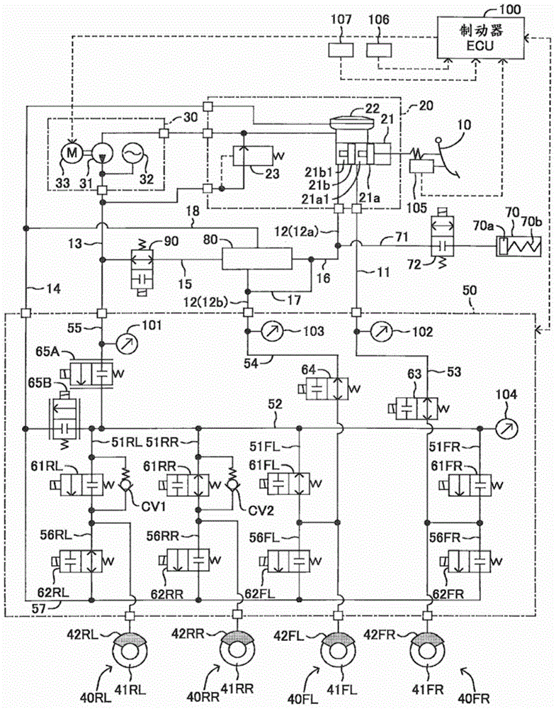
[0038] Hereinafter, a brake device for a vehicle according to an embodiment of the present invention will be described with reference to the drawings. figure 1 It is a schematic system diagram of the brake device of the vehicle concerning embodiment.

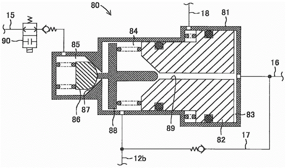
[0039] The braking device of the vehicle is composed of a brake pedal 10, a master cylinder unit 20, a power hydraulic pressure generating device 30, a braking unit 40, a hydraulic control valve device 50, a booster mechanism 80, and a brake ECU 100 for brake control. .

[0040] The master cylinder unit 20 includes a master cylinder 21 and a reservoir 22 . The master cylinder 21 is a tandem type including pressurizing pistons 21a, 21b, and generates master cylinder pressures Pmc_FR, Pmc_FL each having a predetermined boost ratio with respect to a pedaling force input with the pedaling operation of the brake pedal 10 . On the upper part of the master cylinder 21, a reservoir 22 for storing working fluid is provided. Thus, in t...


PUM


Abstract

In individual flow passageways (51) connecting a main flow passageway (52) connected to an accumulator (32) of a power fluid pressure generation device (30) with wheel cylinders (42), holding valves (61) are disposed. The holding valves (61) permit communication between an upstream side and a downstream side in an open valve state to transmit a fluid pressure from the accumulator (32) to the wheel cylinders (42), while disconnecting the upstream side and the downstream side in a closed valve state. Of the holding valves (61), the holding valves (61RR, 61RL) disposed in left and right rear-wheel brake systems in which the fluid pressure on the main flow passageway (52) side (upstream side) to which the fluid pressure is transmitted from the accumulator (32) is not less than the fluid pressure on the wheel cylinder (42) side (downstream side) at all times are provided with check valves (CV1, CV2) in parallel for reducing the fluid pressure of the wheel cylinders (42) by permitting communication only from the downstream side to the upstream side.

Description

technical field [0001] The present invention relates to a braking device for a vehicle. The braking device for a vehicle includes: a master cylinder that generates hydraulic pressure corresponding to the driver's operation of a brake pedal; a power hydraulic pressure source that drives a booster pump, The power hydraulic source generates hydraulic pressure; the valve mechanism is composed of a plurality of electromagnetic valves controlled by electric signals, and the hydraulic pressure output from the master cylinder or the power hydraulic source is transmitted to the valve mechanism a wheel cylinder, the hydraulic pressure output from the master cylinder or the power hydraulic source is transmitted to the wheel cylinder through the valve mechanism, so that the wheel cylinder applies a braking force to the wheel; and a control unit, the control The unit controls the action of the valve mechanism. Background technique [0002] In recent years, there have been proposed brake...

Claims


Application Information

Patent Timeline
Patent Type & Authority Applications(China)
IPC IPC(8): B60T8/17B60T8/48B60T17/22
CPCB60T13/686B60T7/042B60T8/4081B60T13/142B60T13/146B60T13/662B60T2270/604
Inventor 宫崎彻也
Owner TOYOTA JIDOSHA KK
Why Eureka
Try Eureka