container
A container and container body technology, applied in the field of containers, can solve the problems of high production and installation costs, waste, and difficult recycling of containers, and achieve the effect of reducing production costs and reducing consumption
- Summary
- Abstract
- Description
- Claims
- Application Information
AI Technical Summary
Problems solved by technology
Method used
Image
Examples
Embodiment 1
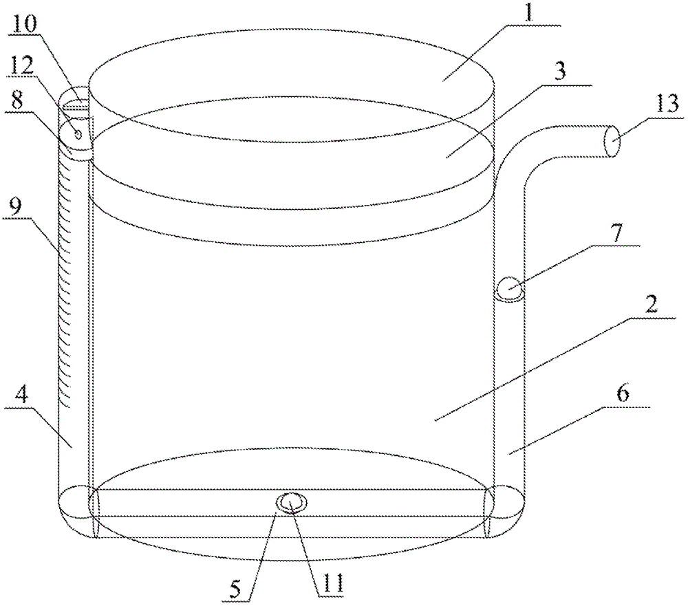
[0073] Such as figure 1 Shown is a container according to Embodiment 1 of the present invention. The main body part 1 of the container is cylindrical and contains a liquid content 2 inside. A piston 3 is placed on the top of the liquid content. The piston 3 can move up and down in the main body part 1 . On the side wall of the main body part 1, a pressure channel composed of a pressure transmission channel 4, an extraction channel 5 and an outflow channel 6 connected in series is attached to the side wall and the bottom wall of the main part.
[0074] The pressure transmission channel 4 is made of a transparent material with a scale 9 marked on it. There is a piston 8 on the upper port of the pressure transmission channel 4, the piston 8 can move downward along the pressure transmission channel 4, and the baffle plate 10 prevents the piston 8 from moving upward. Screw hole 12 is arranged on piston 8, can connect pressure rod.
[0075] There is a one-way valve 11 on the extr...
Embodiment 2
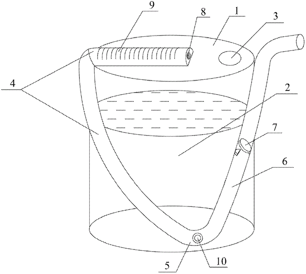
[0079] Such as figure 2 Shown is a kind of container according to embodiment 2. The container includes a container main body 1 with a filling opening on the upper part of the container main body 1. After filling the content 2, the filling opening is sealed with a film 3 that only allows small molecule gas to pass through.
[0080] The container also includes a pressure channel obliquely attached to the upper wall and side wall of the container body 2. The pressure channel is composed of a pressure transmission channel 4, an extraction channel 5 and an outflow channel 6 connected in series, and the pressure channels are located on the same plane. A part of the pressure transmission channel 4 is located on the upper wall of the container body 1 , and a part is located on the side wall of the container body 1 . The one-way valve 10 on the extraction passage 5 is located at the lowest end of the pressure passage, and opens at a low place inside the main body of the container. T...
Embodiment 3
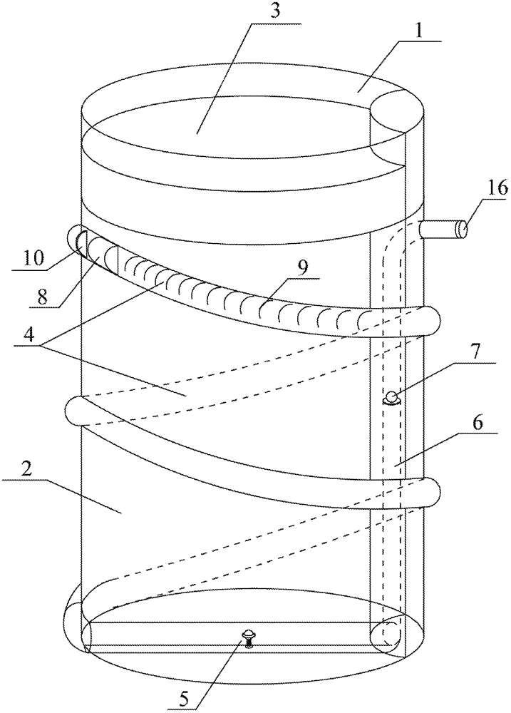
[0084] Such as image 3 , Figure 4 As shown, it is a container for containing contents according to embodiment 3, Figure 4 An enlarged view of a one-way valve. The main part 1 of the container is cylindrical, and contains a liquid content 2. There is a piston 3 on the liquid content, and the piston 3 can move up and down in the main part 1. On the side wall of the main body part 1, a pressure channel composed of a pressure transmission channel 4, an extraction channel 5 and an outflow channel 6 connected in series is attached to the side wall and the bottom wall of the main part. Wherein, the pressure transmitting channel 4 is spirally attached to the outer wall of the main body, the outflow channel 6 is attached to the inner wall of the main body, and the opening of the outflow channel 6 is located outside the container.
[0085] The pressure transmission channel 4 is made of a transparent material with a scale 9 marked on it. There is a piston 8 on the upper port of th...
PUM
 Abstract
Description
Claims
Application Information
 - R&D
- Intellectual Property
- Life Sciences
- Materials
- Tech Scout
- Unparalleled Data Quality
- Higher Quality Content
- 60% Fewer Hallucinations
Browse by: Latest US Patents, China's latest patents, Technical Efficacy Thesaurus, Application Domain, Technology Topic, Popular Technical Reports.
© 2025 PatSnap. All rights reserved.Legal|Privacy policy|Modern Slavery Act Transparency Statement|Sitemap|About US| Contact US: help@patsnap.com


