Container

A container and container body technology, applied in the field of containers, can solve the problems of high production and installation costs, waste, and difficult recycling of containers, and achieve the effect of reducing production costs and reducing consumption

Active Publication Date: 2015-07-01
BEIJING RED SEA TECH
View PDF5 Cites 0 Cited by
  • Summary
  • Abstract
  • Description
  • Claims
  • Application Information

AI Technical Summary

Problems solved by technology

This has caused a lot of environmental pollution and waste
[0006] For example, for a container taken out by a presser, the main body of the container and the presser are produced separately and then used in combination. The structure of the presser is complex and cannot be integrated with the container, which makes the production and installation costs of the container higher; When finished, both the extractor part and the container body are discarded as trash
The way the extractor goes deep into the container makes it difficult to recycle after the extractor is contaminated with the contents
[0007] These commonplace problems are easily overlooked

Method used


Image

  • Container
  • Container
  • Container

Examples


Embodiment 1

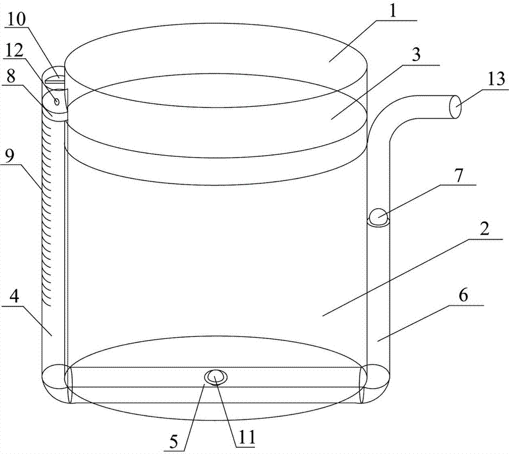
[0068] Such as figure 1 Shown is a container according to Embodiment 1 of the present invention. The main body part 1 of the container is cylindrical and contains a liquid content 2 inside. A piston 3 is placed on the top of the liquid content. The piston 3 can move up and down in the main body part 1 . On the side wall of the main body part 1, a pressure channel composed of a pressure transmission channel 4, an extraction channel 5 and an outflow channel 6 connected in series is attached to the side wall and the bottom wall of the main part.

[0069] The pressure transmission channel 4 is made of a transparent material with a scale 9 marked on it. There is a piston 8 on the upper port of the pressure transmission channel 4, the piston 8 can move downward along the pressure transmission channel 4, and the protrusion 10 prevents the piston 8 from moving upward. Screw hole 12 is arranged on piston 8, can connect pressure rod.

[0070] There is a one-way valve 11 on the extrac...

Embodiment 2

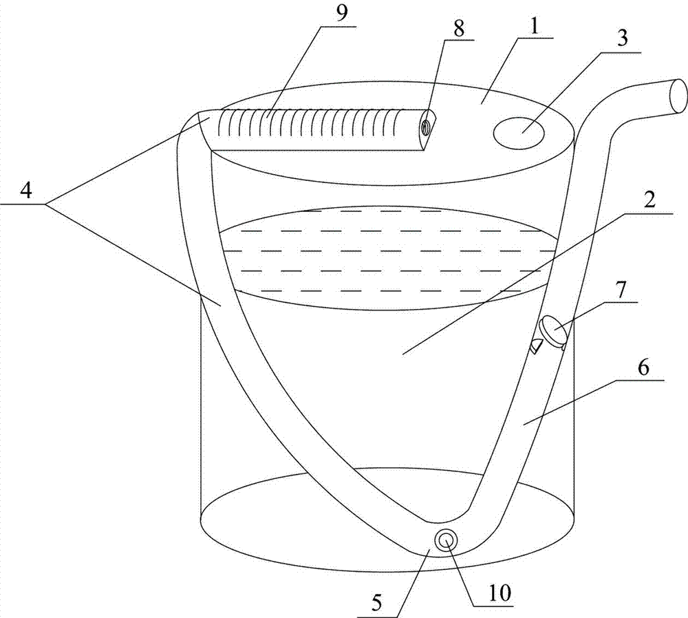
[0074] Such as figure 2 Shown is a kind of container according to embodiment 2. The container includes a container main body 1 with a filling opening on the upper part of the container main body 1. After filling the content 2, the filling opening is sealed with a film 3 that only allows small molecule gas to pass through.

[0075] The container also includes a pressure channel obliquely attached to the upper wall and side wall of the container body 2. The pressure channel is composed of a pressure transmission channel 4, an extraction channel 5 and an outflow channel 6 connected in series, and the pressure channels are located on the same plane. A part of the pressure transmission channel 4 is located on the upper wall of the container body 1 , and a part is located on the side wall of the container body 1 . The one-way valve 10 on the extraction passage 5 is located at the lowest end of the pressure passage, and opens at a low place inside the main body of the container. T...

Embodiment 3

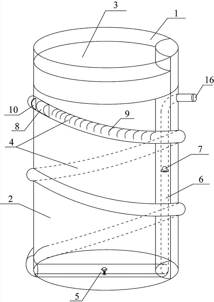
[0079] Such as image 3 , Figure 4 As shown, it is a container for containing contents according to embodiment 3, Figure 4 An enlarged view of a one-way valve. The main part 1 of the container is cylindrical, and contains a liquid content 2. There is a piston 3 on the liquid content, and the piston 3 can move up and down in the main part 1. On the side wall of the main body part 1, a pressure channel composed of a pressure transmission channel 4, an extraction channel 5 and an outflow channel 6 connected in series is attached to the side wall and the bottom wall of the main part. Wherein, the pressure transmitting channel 4 is spirally attached to the outer wall of the main body, the outflow channel 6 is attached to the inner wall of the main body, and the opening of the outflow channel 6 is located outside the container.

[0080] The pressure transmission channel 4 is made of a transparent material with a scale 9 marked on it. There is a piston 8 on the upper port of th...


PUM


Abstract

The invention provides a container. The container comprises a container body, a pressure application component and a pressure channel, wherein the pressure channel is formed by a pressure transmission channel, an object fetching channel and a flowing-out channel in a series connection mode. A body of the pressure channel is attached to the wall of the container body. The pressure application component is used for applying pressure into the pressure transmission channel. The pressure transmission channel transmits the pressure applied by the pressure application component through a pressure transmission medium inside the pressure transmission channel. The object fetching channel is provided with a one-way valve which allows a contained object in the container body to flow into the pressure channel. The flowing-out channel is a channel for allowing the contained object to flow out of the container and can prevent the contained object from back flow. An opening of the one-way valve of the object fetching channel is formed in the bottom in the container body. The joint of the pressure application component and the pressure transmission channel is higher than the liquid surface of the contained object in the container body. The container is low in manufacturing cost, users can conveniently and quantificationally fetch the contained object, the contained object can be prevented from being oxidized or polluted, and environment pollution is reduced.

Description

technical field [0001] The invention relates to a container capable of taking out the contents in the container conveniently and quickly. Background technique [0002] In today's life, people's daily life products are increasingly abundant, liquid and paste products such as hand sanitizer, laundry detergent, disinfectant, shampoo, shower gel, toothpaste, soy sauce, vinegar, edible oil, liquid medicine, cosmetics, health care products, etc. increasingly rich. However, although the containers for holding the above-mentioned products are of various shapes, innovative structures are very few, there is no major improvement over the years, and many problems of existence have been taken for granted. [0003] For example, there is no quantitative container in life. When people have to take out quantitatively, they often use other graduated containers to realize quantitatively, and sometimes use a rough measurement method such as "2.5 bottle caps". This one is inconvenient to oper...

Claims


Application Information

Patent Timeline
Patent Type & Authority Patents(China)
IPC IPC(8): B65D83/76
Inventor 不公告发明人
Owner BEIJING RED SEA TECH
Why Eureka
Try Eureka