Medium-drive dirt cleaning machine for transmission pipelines

A technology of conveying pipeline and cleaning machine, applied in the field of machinery, can solve the problems of removing the dirt of conveying pipeline, and achieve the effect of good cutting effect and high efficiency

Inactive Publication Date: 2015-05-13
冯洪仁
View PDF10 Cites 12 Cited by
  • Summary
  • Abstract
  • Description
  • Claims
  • Application Information

AI Technical Summary

Problems solved by technology

Solve the technical problems of dirt removal in pipelines

Method used


Image

  • Medium-drive dirt cleaning machine for transmission pipelines
  • Medium-drive dirt cleaning machine for transmission pipelines

Examples


Embodiment 1

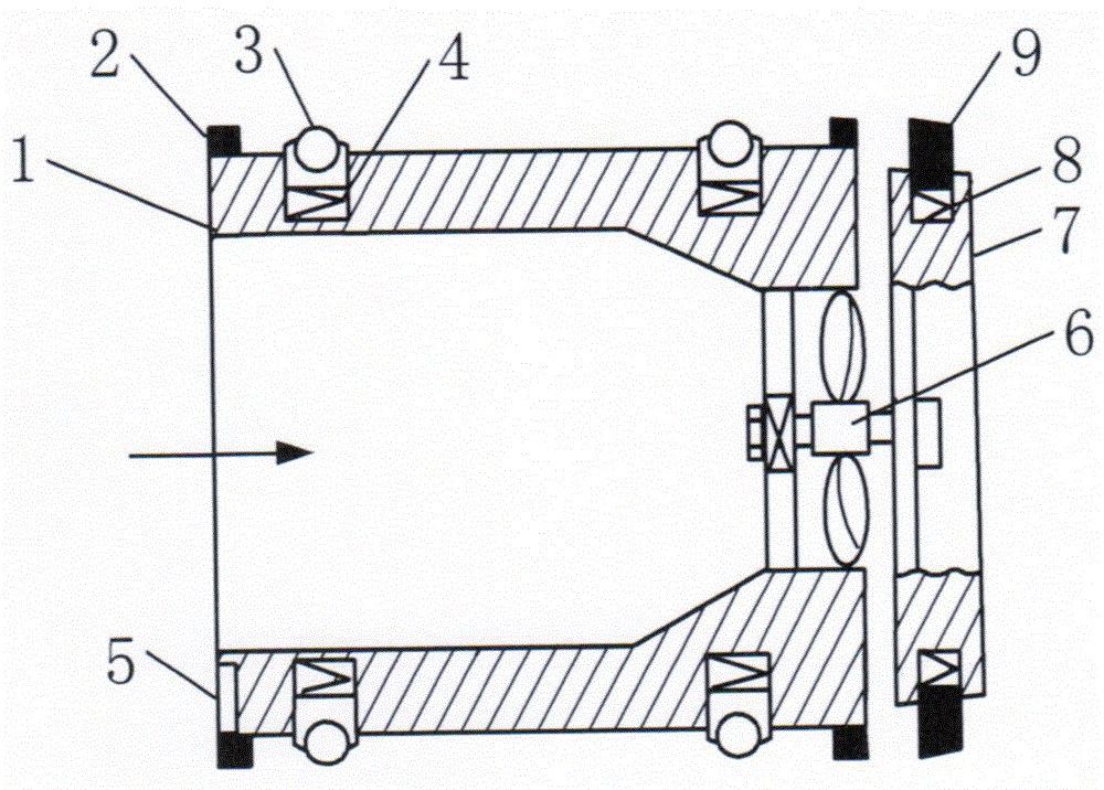
[0011] according to figure 1 As shown, sealing rings 2 are set on the front and rear sides of the cylinder body 1, and the walking support wheel 3 is installed through the compensation spring 4. The cutting head 7 is installed on the front of the cylinder body through the rotating shaft, and the cutting head ring passes through the cutter spring 8. A cutting tool 9 is installed.

[0012] A positioning sensor 5 is installed on the cylinder wall.

[0013] The driving rotating mechanism 6 is an impeller.

[0014] The front end of the barrel is provided with a conical diversion chamber.

[0015] The diversion cavity increases the flow rate of the liquid passing through the cylinder, and the generated rotational force and torque are large, which can make the cutting head rotate with a relatively large torque.

Embodiment 2

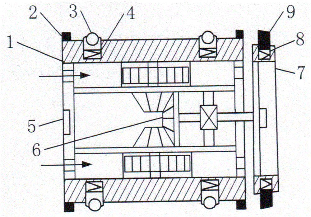
[0017] according to figure 2 As shown, there are blocking plates on both sides of the cylinder, medium inlets and medium outlets on the blocking plates, and impellers are installed in the formed diversion cavity, which are connected with bevel gears. The bevel gear is meshed with the bevel gear for transmission connection, and the bevel gear is installed and connected with the cutting head through a shaft.

[0018] The driving rotation mechanism is driven by impeller, bevel gear and bevel gear. The diversion cavity is arranged on the front and rear blocking plates.

[0019] When the bevel gear and the bevel gear are meshed for transmission, when the cutting head has a large torque and stalls, the cylinder is pushed forward by the medium to increase the thrust.

[0020] Positioning sensors are installed on the blocking plate.

[0021] The cutting head is a conical body, and the outer edge is provided with one to three layers of cutting tools arranged at a distance.

[0022...


PUM


Abstract

The invention provides a medium-drive dirt cleaning machine for transmission pipelines. The medium-drive dirt cleaning machine is characterized in that sealing rings sleeve the front side and the rear side of a barrel, the barrel is provided with traveling support wheels via compensating springs, a cutting head is mounted at the front of the barrel via a rotary shaft, and cutters are mounted on the annular periphery of the cutting head via cutter springs; a positioning sensor is arranged on the barrel, a driving rotary mechanism is arranged in the barrel, and impeller or impeller and bevel gear transmission effects can be realized by the driving rotary mechanism. The medium-drive dirt cleaning machine has the advantages that an impeller can rotate under the effects of media in the transmission pipelines, so that the cutters can be driven to rotate to cut dirt; the medium-drive dirt cleaning machine has automatic traveling, automatic switching and automatic dirt cleaning functions, has automatic tracking positioning and unmanned operation ability and is suitable for the transmission pipelines for petroleum or other medium.

Description

technical field [0001] The invention proposes a medium-driven dirt removal machine for conveying pipelines in the mechanical field. Background technique [0002] Before the present invention was proposed, it was not found that there was no power self-driven conveying pipeline dirt removal machine was published or actually used, but the dirt retention in the conveying pipeline will affect the conveying capacity of the conveying medium, and with the accumulation of dirt, the conveying medium will increase The transmission resistance increases energy consumption. Contents of the invention [0003] In order to realize the removal of dirt on the inner wall of the pipeline by using the liquid flow of the transmission medium as the power, the invention provides a medium-driven dirt removal machine for the transmission pipeline. The machine drives the power mechanism to rotate through the medium, and drives the cutting tool to rotate to remove dirt. Solve the technical problem o...

Claims


Application Information

Patent Timeline
Patent Type & Authority Applications(China)
IPC IPC(8): B08B9/055
CPCB08B9/055
Inventor 冯洪仁
Owner 冯洪仁
Why Eureka
Try Eureka