Extruding method for two-dimension function-variation continuous variable-cross-section profile

An extrusion method and continuous technology, applied in the field of two-dimensional function-variable continuous variable-section profile extrusion, can solve problems such as difficulty in ensuring forming accuracy, and achieve the effects of high production efficiency, accurate size control, and simple equipment

Active Publication Date: 2015-05-13
NO 59 RES INST OF CHINA ORDNANCE IND
View PDF5 Cites 14 Cited by
  • Summary
  • Abstract
  • Description
  • Claims
  • Application Information

AI Technical Summary

Problems solved by technology

However, this method can only realize the extrusion forming of prefabricated simple sections. For profiles that need to have a continuously distributed surface that changes in a function curve, this method is difficult to ensure the forming accuracy; and in engineering, only short-length variable-section profiles can be formed.

Method used


Image

  • Extruding method for two-dimension function-variation continuous variable-cross-section profile
  • Extruding method for two-dimension function-variation continuous variable-cross-section profile
  • Extruding method for two-dimension function-variation continuous variable-cross-section profile

Examples


Embodiment 1

[0025] 1. Machining 2024 aluminum alloy raw materials into prefabricated blank size;

[0026] 2. Keep the prefabricated blank in the temperature range of 450-470°C for 2 hours;

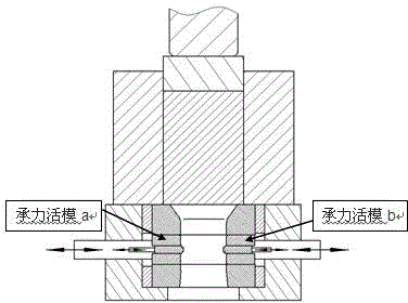
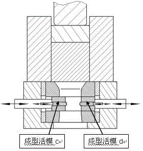
[0027] 3. Control the temperature of the extrusion cylinder and the molding die at 430-450°C; complete the adjustment of the motion control servo device, the load-bearing die and the forming die. That is to ensure that the maximum gap between the load-bearing mold a and the load-bearing mold b is smaller than the cavity size of the mold, and the minimum gap is greater than zero; ensure that the maximum gap between the forming mold c and the forming mold d is smaller than the mold cavity size, and the minimum gap is equal to the mold cavity size The minimum dimension in the direction of the cross section; to ensure that the forming mold lags behind the matching bearing mold for 1 second when it is fed inward, and ensures that the forming mold is ahead of the matching bearing mold for 1 second when it w...

Embodiment 2

[0032] 1. Machining 6061 aluminum alloy raw materials into prefabricated billet size;

[0033] 2. Heat the 6061 aluminum alloy prefabricated billet in the temperature range of 500-520°C for 1.5 hours;

[0034] 3. Control the temperature of the extrusion cylinder and the molding die at 490-500°C; complete the adjustment of the motion control servo device, the load-bearing mold and the forming mold. That is to ensure that the maximum gap between the load-bearing mold a and the load-bearing mold b is smaller than the cavity size of the mold, and the minimum gap is greater than zero; ensure that the maximum gap between the forming mold c and the forming mold d is smaller than the mold cavity size, and the minimum gap is equal to the mold cavity size The minimum size in the direction of the cross section; ensure that the forming die lags behind the matching load-bearing die by 0.5 seconds when it is fed inward, and ensures that the forming die is ahead of the matching load-bearing ...

Embodiment 3

[0039] 1. The AZ31 magnesium alloy raw material is machined into prefabricated billet size;

[0040] 2. Keep the AZ31 magnesium alloy prefabricated blank in the temperature range of 380-390°C for 1 hour;

[0041] 3. Control the temperature of the extrusion cylinder and the molding die within 370-480°C; complete the adjustment of the motion control servo device, the load-bearing mold and the forming mold. That is to ensure that the maximum gap between the load-bearing mold a and the load-bearing mold b is smaller than the cavity size of the mold, and the minimum gap is greater than zero; ensure that the maximum gap between the forming mold c and the forming mold d is smaller than the mold cavity size, and the minimum gap is equal to the mold cavity size The minimum size in the direction of the cross section; ensure that the forming die lags behind the matching load-bearing die by 0.75 seconds when it is fed inward, and ensures that the forming die is ahead of the matching load-...


PUM


Abstract

The invention provides an extruding method for a two-dimension function-variation continuous variable-cross-section profile, and aims at solving the forming problem of a continuous variable-cross-section member showing function variation along the length direction. By coordinating the rapid response cooperation motion among a bearing segmented die, a molding segmented die and an extrusion rod, controllable continuous variable-cross-section precise molding for a member which possesses a relatively large length-diameter ratio and has the cross section shape relatively substantially changing along the profile length direction is realized.

Description

technical field [0001] The invention relates to a metal profile processing method, in particular to a two-dimensional function variable continuous variable section profile extrusion method. Background technique [0002] With the increasing demand for lightweight industrial equipment, aluminum alloys and magnesium alloys have been widely used in the transportation industry, electronics industry, medical field, military industry and aerospace fields in recent years. However, if the light metal material is directly replaced with the steel part, the low comprehensive strength and stiffness of the light metal material will be difficult to meet the requirements of the original part, which requires a large plastic deformation to increase the strength of the light metal material , and high-efficiency and low-energy-consuming part structure forming process to ensure reliable performance and controllable cost of light metal weapon components. Especially for parts with a large long-di...

Claims


Application Information

Patent Timeline
Patent Type & Authority Applications(China)
IPC IPC(8): B21C23/14B21C25/08
Inventor 陈强万元元林军刘川林舒大禹赵高瞻赵祖德柴舒心车路长
Owner NO 59 RES INST OF CHINA ORDNANCE IND
Why Eureka
Try Eureka