Fixture for detecting errors of transmission wave surface of large-sized neodymium glass plate

An error detection and neodymium glass technology is applied in the field of clamping devices for error detection of large-size neodymium glass sheets transmitted wavefront, and achieves the effects of convenient angle adjustment, safe clamping, and convenient movement.

Inactive Publication Date: 2015-05-13
LASER FUSION RES CENT CHINA ACAD OF ENG PHYSICS
View PDF8 Cites 12 Cited by
  • Summary
  • Abstract
  • Description
  • Claims
  • Application Information

AI Technical Summary

Problems solved by technology

Although the fixture is simple and lightweight, it is flexible and convenient to operate, and has high repeat positioning accuracy, which ensures the precision of mold spray welding. During the clamping process, it is necessary to constantly adjust the placement angle of the large-size neodymium glass piece
[0004] In the prior art, when the large-size neodymium glass sheet is used to detect the trans

Method used


Image

  • Fixture for detecting errors of transmission wave surface of large-sized neodymium glass plate
  • Fixture for detecting errors of transmission wave surface of large-sized neodymium glass plate
  • Fixture for detecting errors of transmission wave surface of large-sized neodymium glass plate

Examples


Embodiment 1

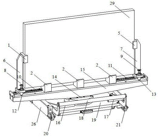
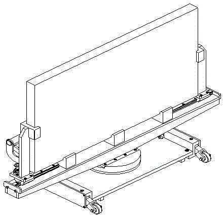
[0029]A large-size neodymium glass plate transmission wavefront error detection fixture includes a base 19, a base turntable 14 is arranged on the top surface of the base 19, and the base turntable 14 can rotate freely on the base 19. The connection mode between the base 19 and the base turntable 14 is: the base 19 and the connection pins above the base 19 are fixedly connected by screws, the base turntable 14 is sleeved on the connection pins and positioned by the shoulders of the connection pins, and the base turntable 14 The aperture is slightly larger than the diameter of the connecting pin, so the base rotating disk 14 can rotate freely around the axis of the connecting pin. In addition, a thrust bearing can also be set between the base rotating disk 14 and the base 19, and the distance between the two can be moved by the thrust bearing. The surface contact is changed to rolling contact, which effectively reduces the friction between the base turntable 14 and the base 19 ,...

Embodiment 2

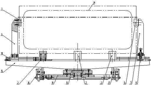
[0032] On the basis of Embodiment 1, a number of left limit holes 12 are provided on the support frame 15 near the end of the I-shaped left slide rail 10, and some left limit holes 12 are located on the same side of the I-shaped left slide rail 10. The limiting holes 12 are arranged along the length direction of the I-shaped left slide rail 10 . One end near the right slide rail 11 of the I-type on the bracing frame 15 is provided with some right limit holes 13, and some right limit holes 13 are positioned at the same side of the I-type right slide rail 11, and some right limit holes 13 are along the right side of the I-type. The lengthwise direction of the slide rails 11 is arranged. Left support arm 6 bottom is connected with left screw rod 8, and the outer diameter of left screw rod 8 is compatible with the inner diameter of left limit hole 12, when needing to move left support arm 6, lift left screw rod 8 to make left screw rod 8 stop from the left Break away from the hol...

Embodiment 3

[0035] On the basis of the first or second embodiment, the two sides of the base 19 are also provided with traveling mechanisms. This walking mechanism comprises left lifting roller cover 26, right lifting roller cover 27, left lifting roller 20, right lifting roller 21, handle 18, left lever 16 and right lever 17. The left lifting roller cover 26 is fixedly connected to the left side of the base 19, and the right lifting roller cover 27 is fixedly connected to the right side of the base 19. The central position of left lifting roller cover 26 and right lifting roller cover 27 all offers the rectangular through hole that is used to place lifting roller, makes left lifting roller cover 26 and right lifting roller cover 27 form " back " font structure. The left lifting roller 20 is placed in the rectangular through hole of the left lifting roller cover 26, the left lifting roller 20 can move up and down along the height direction of the left lifting roller cover 26, and the fron...


PUM


Abstract

The invention discloses a fixture for detecting errors of a transmission wave surface of a large-sized neodymium glass plate, and relates to a clamping device for detecting errors of transmission wave surfaces of large-sized neodymium glass plates in the technical field of special-purpose fixtures. By the fixture for detecting the errors of the transmission wave surface of the large-sized neodymium glass plate, the large-sized neodymium glass plate can be clamped safely, and a placing angle can be adjusted conveniently and quickly. The fixture comprises a base, wherein two sides of the base are connected with travelling mechanisms; the top of the base is connected with a base rotating plate; the top of the base rotating plate is connected with a support frame; the support frame can rotate around the axis of the base along with the base rotating plate; an H-shaped left sliding track, a bottom concave clamping block and an H-shaped right sliding track are sequentially arranged on the top of the support frame from left to right; the H-shaped left sliding track is provided with a left supporting arm capable of moving along the length direction of the H-shaped left sliding track; a left concave clamping block is arranged on the left supporting arm; a right supporting arm capable of moving along the length direction of the H-shaped right sliding track is arranged on the H-shaped right sliding track; and a right concave clamping block is arranged on the right supporting arm.

Description

technical field [0001] The invention belongs to the technical field of special fixtures, and relates to a clamping device for large-size neodymium glass sheet transmission wave surface error detection, in particular to a device capable of realizing safe clamping, convenient placement angle adjustment and moving transfer of large-size neodymium glass sheets at the same time fixture. Background technique [0002] Large-size neodymium glass is a key component in large-scale high-power solid-state laser devices, and its performance index directly affects the output laser power and beam quality of the entire laser device, and the transmission wavefront error of large-size neodymium glass is the key One of the performance indicators. Large-size neodymium glass sheets need to be placed at specific angles when detecting transmission wavefront errors, so fixtures are required to clamp and fix large-size neodymium glass sheets. [0003] At present, most of the clamping of glass occu...

Claims


Application Information

Patent Timeline
IPC IPC(8): B25B11/00
CPCB25B5/003B25B5/145B25B11/00G01M11/00
Inventor 杨一任寰马可张霖原泉石振东马骅马玉荣冯晓璇
Owner LASER FUSION RES CENT CHINA ACAD OF ENG PHYSICS
Why Eureka
Try Eureka