Supercharge Your Innovation With Domain-Expert AI Agents!

Elevator speed limiter and control method thereof

An elevator speed limiter and speed limiter technology, applied in elevators, transportation and packaging, etc., can solve the problems of low accuracy, complicated mechanical structure, and heavy calibration workload, and achieve accurate speed measurement, simple mechanical structure, The effect of prolonging the verification period

Inactive Publication Date: 2015-05-13
HEFEI UNIV OF TECH
View PDF10 Cites 4 Cited by
  • Summary
  • Abstract
  • Description
  • Claims
  • Application Information

AI Technical Summary

Problems solved by technology

[0004] 1. The mechanical structure is complex and the movement speed is not precise, so it can only be adjusted within a certain speed range
[0005] 2. The action speed needs to be checked regularly, otherwise reliable triggering cannot be guaranteed
The temperature, humidity, dust and corrosive gas of the environment where the elevator is used may reduce the mechanical action speed of the speed limiter or even cause the mechanism to rust, and the spring will also be fatigued due to stretching and compression. The speed of the accelerator slows down
When the elevator runs at overspeed, the braking lags or even fails, which may cause personal accidents or property losses. Therefore, it is necessary to regularly use special instruments to check the action speed of the mechanical elevator speed limiter. Heavy workload, cumbersome operation and low accuracy
[0006] 3. After the speed limiter produces a speed limit action, it is necessary to manually reset the emergency stop switch and the mechanical trigger mechanism, which increases the complexity of maintenance

Method used


Image

  • Elevator speed limiter and control method thereof
  • Elevator speed limiter and control method thereof
  • Elevator speed limiter and control method thereof

Examples


Embodiment Construction

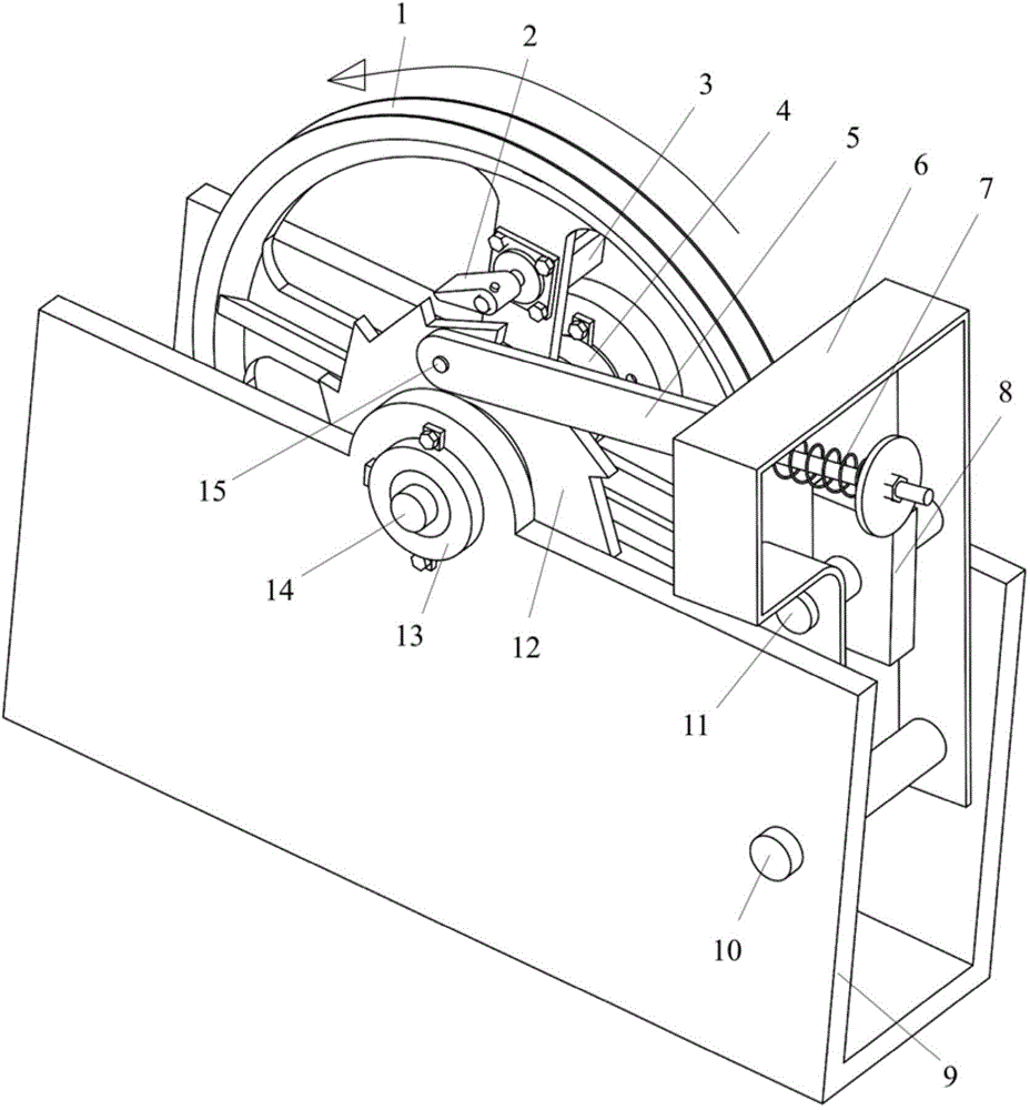
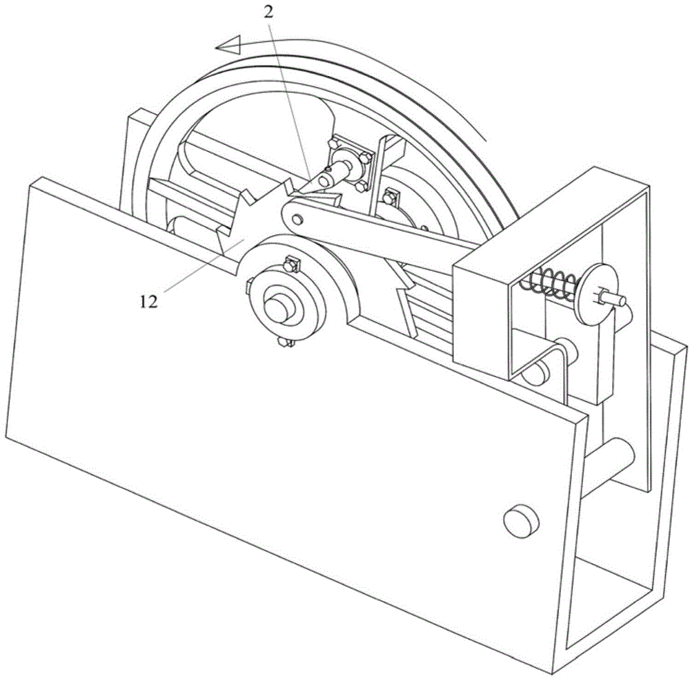
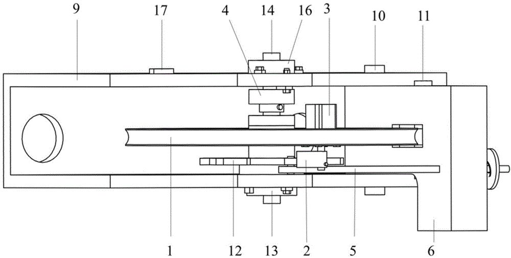
[0034] see figure 1 , figure 2 , image 3 and Figure 4 , the structural form of the elevator overspeed governor in the present embodiment is:

[0035] A "U"-shaped frame 9 composed of two side plates and a bottom plate is set, and the first bearing 18 and the second bearing 19 are used to support the rotating shaft 14 on the two side plates of the frame 9; the speed limiter wheel is fixedly arranged on the rotating shaft 14 Disc 1, the steel wire rope is wound in the upper half of the wheel groove of the speed governor wheel 1, and the movement of the elevator car drives the speed governor wheel 1 to rotate together with the rotating shaft 14 through the steel wire rope and the friction force; the third bearing on the rotating shaft 14 20 is equipped with a ratchet 12, the ratchet 12 can rotate around the shaft 14, the ratchet 12 is located between the speed limiter wheel 1 and the side plate of the frame 9; a photoelectric encoder 13 is arranged on the rotating shaft 14,...


PUM


Abstract

The invention discloses an elevator speed limiter and a control method of the elevator speed limiter. The elevator speed limiter is characterized in that a rotating shaft is supported on two side plates of a rack through bearings; a limiter wheel dish is fixedly arranged on the rotating shaft, a steel wire rope is wound around an upper half wheel groove in the limiter wheel dish, and an elevator lift car moves to drive the limiter wheel dish to rotate together with the rotating shaft through the steel wire rope by the utilization of friction force; the rotating shaft is sleeved with a ratchet wheel through a bearing, the ratchet wheel can rotate around the rotating shaft, and a photoelectric encoder is used for detecting the rotation speed of the limiter wheel dish; a pawl is arranged in cooperation with the ratchet wheel, and a stepping motor is fixedly arranged on a spoke of the limiter wheel dish and controls the pawl to rotate; a brake mechanism driven by a connecting rod is arranged, and the brake mechanism and the limiter wheel dish together clamp the steel wire rope to implement braking. The elevator speed limiter is simple in speed limiting structure and reliable in operation.

Description

technical field [0001] The invention relates to an elevator speed governor and a control method thereof. Background technique [0002] Elevators are means of transportation that run vertically in space, and the reliable operation of elevators is crucial to the safety of passengers and goods. The main component that controls the safe operation of the elevator within the rated speed is the speed limiter of the elevator. The speed limiter is a necessary safety guarantee component for every elevator. When the elevator runs out of control at overspeed, for example, when the traction wire rope breaks or the elevator control system fails, the speed limiter should act immediately to send an emergency stop signal, and drive the wire rope through the speed limiter to pull the safety gear to stop the elevator car at running on the track and avoid accidents in time. [0003] Most of the elevator overspeed governors in the prior art are purely mechanically controlled, and are mainly co...

Claims


Application Information

Patent Timeline
IPC IPC(8): B66B5/06B66B5/24
CPCB66B5/044B66B5/06B66B5/24
Inventor 王玉琳马俊文强劲李智金左雨
Owner HEFEI UNIV OF TECH
Features
  • R&D
  • Intellectual Property
  • Life Sciences
  • Materials
  • Tech Scout
  • Unparalleled Data Quality
  • Higher Quality Content
  • 60% Fewer Hallucinations
Learn More