
Heat treatment mechanism for metallurgical workpieces

A workpiece and box technology, applied in the field of heat treatment mechanism, can solve the problems of uneven cooling, uncontrollable cooling rate, affecting the quality of heat treatment, etc., to achieve the effect of good cooling and control of cooling rate

Inactive Publication Date: 2015-05-13
CHANGZHOU NEW SCI METALLURGY MATERIALS
View PDF0 Cites 0 Cited by
  • Summary
  • Abstract
  • Description
  • Claims
  • Application Information

AI Technical Summary

Problems solved by technology

Although the two methods can cool the workpiece at a certain speed, when cooling large workpieces, these two methods will cause the problem of uneven cooling and affect the quality of heat treatment. At the same time, when the two methods are cooling, the cooling rate cannot control

Method used


Image

  • Heat treatment mechanism for metallurgical workpieces

Examples


Embodiment Construction

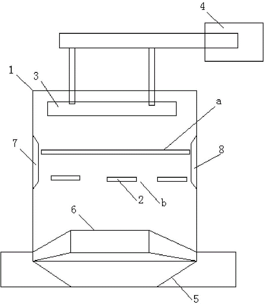
[0009] Such as figure 1 As shown, the heat treatment mechanism for metallurgical workpieces includes a workpiece cooling box 1, and the upper end of the workpiece cooling box 1 is provided with two distribution plate groups a and b, and each distribution plate group includes three distribution plates 2 arranged in parallel. , the two-layer distribution plate group is vertically arranged in space, at least one aerosol generator 3 is arranged on the top of the workpiece cooling box 1, the aerosol generator 3 is connected to the water pump 4, and the bottom of the workpiece cooling box 1 is provided with a water collection tank 5 and The blowing device 6 of upward blowing.

[0010] The inner walls of both sides of the workpiece cooling box 1 are provided with gas circulation components 7 and 8 .


PUM


Abstract

The invention belongs to the field of metallurgical equipment and specifically relates to a heat treatment mechanism for metallurgical workpieces. The heat treatment mechanism comprises a workpiece cooling box body. An upper end inside the workpiece cooling box body is provided with two layers of distribution plate groups. Each layer of the distribution plate group contains three parallelly arranged distribution plates. The two layers of the distribution plate groups are arranged vertically in the space. The top of the workpiece cooling box body is provided with at least one aerosol generator which is connected with a water pump. The bottom of the workpiece cooling box body is provided with a water collecting tank and a blowing device which blows air upwards. The invention has advantages as follows: as steam from the aerosol generator can be uniformly dispersed through the distribution plates, axial circulation can be formed by a gas cycle unit and longitudinal circulation is formed by the blowing device, workpieces can be better cooled and cooling rate can be controlled.

Description

technical field [0001] The invention belongs to the field of metallurgical equipment, in particular to a heat treatment mechanism for metallurgical workpieces. Background technique [0002] Heat treatment technology is a thermal method commonly used in the machinery industry to improve the mechanical properties of workpieces. The so-called heat treatment is to heat the workpiece to a certain temperature, keep it warm, and then cool it. The cooling methods include oil cooling, water cooling and air cooling. The commonly used method of air cooling is to place the heat-treated workpiece in the air and let it cool naturally. Another method is to use a blower to blow air like the heat-treated workpiece to increase the cooling rate. Although the two methods can cool the workpiece at a certain speed, when cooling large workpieces, these two methods will cause the problem of uneven cooling and affect the quality of heat treatment. At the same time, when the two methods are cooling, ...

Claims


Application Information

Patent Timeline
IPC IPC(8): C21D1/00
CPCC21D1/00
Inventor 邵峰
Owner CHANGZHOU NEW SCI METALLURGY MATERIALS
Learn More