Building anti-continuous collapse reinforcement system and method combined with hpfl and steel plate
A building and steel plate technology, applied in building construction, construction, building maintenance, etc., can solve problems such as affecting structural clearance, damage to original structure construction, and difficulty in fully utilizing the strength of reinforcement materials.
- Summary
- Abstract
- Description
- Claims
- Application Information
AI Technical Summary
Problems solved by technology
Method used
Image
Examples
Embodiment 1
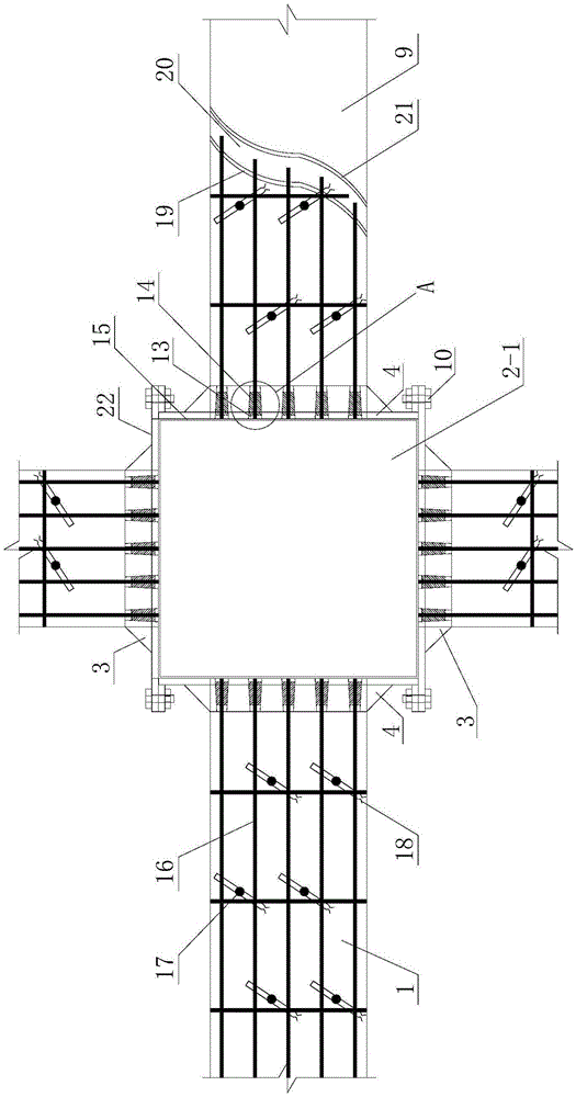
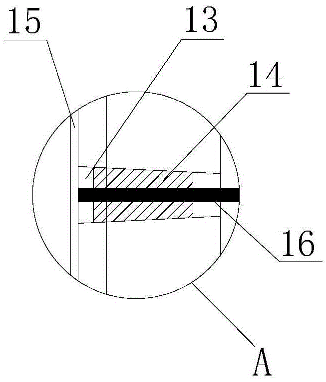
[0070] Such as figure 1 with image 3 As shown, the building anti-continuous collapse reinforcement system combining HPFL and steel plates of the present invention includes a plurality of anchoring steel plates that are pasted on the surface of the column to be reinforced by adhesive steel glue 15 to form a ring and HPFL reinforcement that is arranged on the surface of the beam 1 to be reinforced Layer 9, two adjacent anchor steel plates are fixedly connected by connecting bolts 10, and the surface of each anchor steel plate is provided with an anti-rust coating 22, and the HPFL reinforcement layer 9 includes tension and is arranged on the beam to be reinforced. 1, the stressed reinforcement mesh 16 on the surface, the interface agent layer 19 arranged on the surface of the beam 1 to be reinforced and the stressed reinforcement mesh 16, and the high-performance mortar bonding layer 20 arranged on the surface of the interface agent layer 19, the stressed reinforcement mesh 16 ...
Embodiment 2
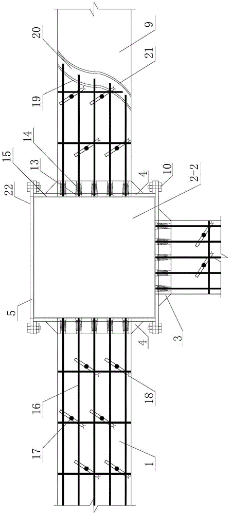
[0077] Such as figure 2 As shown, the difference between this embodiment and Embodiment 1 is that the column to be reinforced 2 is a side column 2-2, and the number of the anchoring steel plates is four, which are symmetrically arranged on the side column 2-2 without a beam. The third anchoring steel plate 5 and the first anchoring steel plate 3 on the side surface opposite to it, and two second anchoring steel plates 4 symmetrically arranged on the other two sides of the side column 2-2; as Figure 5 with Image 6As shown, the first anchoring steel plate 3 includes a rectangular first bottom plate 3-1 and four first connecting ear plates 3-2 arranged on the sides of the four corners of the first bottom plate 3-1, four first The connecting lugs 3-2 are all arranged parallel to the first bottom plate 3-1, and the four first connecting lugs 3-2 are all provided with first threaded holes 3-5 for connecting bolts 10 to pass through; the first A first thickened region 3-3 is pro...
Embodiment 3
[0079] Such as Figure 4 As shown, the difference between this embodiment and Embodiment 1 is that the column to be reinforced 2 is a corner column 2-3, and the number of the anchoring steel plates is four, which are symmetrically arranged on the beamless side of the corner column 2-3 and The third anchoring steel plate 5 and the first anchoring steel plate 3 on the side surface opposite to it, and the fourth anchoring steel plate 6 and the second anchoring steel plate 6 and the second anchoring steel plate symmetrically arranged on the other side of the corner column 2-3 without beams and on the opposite side surface Steel plate 4; as Figure 5 with Image 6 As shown, the first anchoring steel plate 3 includes a rectangular first bottom plate 3-1 and four first connecting ear plates 3-2 arranged on the sides of the four corners of the first bottom plate 3-1, four first The connecting lugs 3-2 are all arranged parallel to the first bottom plate 3-1, and the four first connec...
PUM
| Property | Measurement | Unit |
|---|---|---|
| height | aaaaa | aaaaa |
| thickness | aaaaa | aaaaa |
| height | aaaaa | aaaaa |
Abstract
Description
Claims
Application Information
 - R&D
- Intellectual Property
- Life Sciences
- Materials
- Tech Scout
- Unparalleled Data Quality
- Higher Quality Content
- 60% Fewer Hallucinations
Browse by: Latest US Patents, China's latest patents, Technical Efficacy Thesaurus, Application Domain, Technology Topic, Popular Technical Reports.
© 2025 PatSnap. All rights reserved.Legal|Privacy policy|Modern Slavery Act Transparency Statement|Sitemap|About US| Contact US: help@patsnap.com


