FPGA (field programmable gate array) based time-digital converter
A technology of time digital and converter, which is applied in the direction of electrical unknown time interval measurement, devices and instruments for measuring time interval, and can solve problems such as measurement error of measurement nodes
- Summary
- Abstract
- Description
- Claims
- Application Information
AI Technical Summary
Problems solved by technology
Method used
Image
Examples
Embodiment Construction
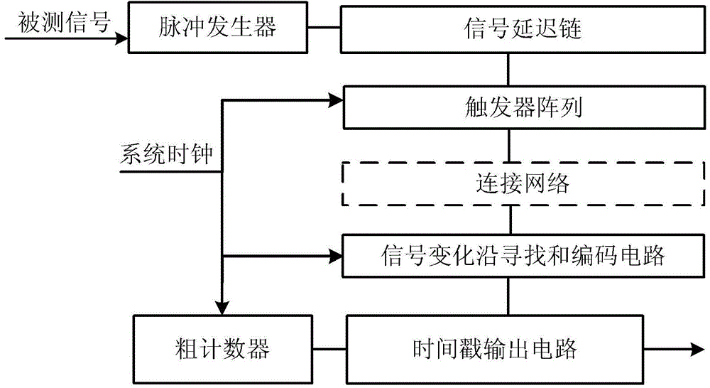
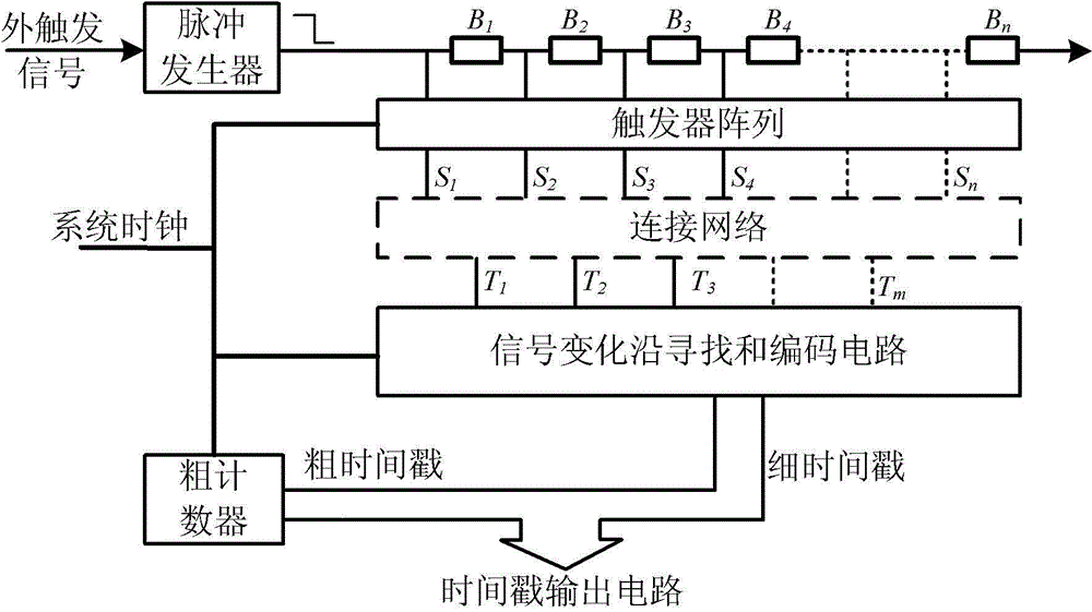
[0050] figure 1 It is a structural schematic diagram of the FPGA-based time-to-digital converter provided by the present invention. Such as figure 1 As shown, it includes a coarse clock counter, a pulse signal generator, a signal delay chain, a flip-flop array, a connection network, a signal change edge search and encoding circuit, and a time stamp output circuit.
[0051] The coarse clock counter is driven by the system clock signal and is used to generate a coarse time stamp of the signal under test.
[0052] The pulse signal generator is externally triggered, which is used to generate a pulse with a changing edge under the trigger of the signal under test and feed it into the signal delay chain for transmission. The changing edge may be a rising edge or a falling edge.
[0053] The signal delay chain is used to delay the transmission of the signal under test. It is composed of multiple delay units and has taps at the front end of each delay unit. Therefore, the signal de...
PUM
 Abstract
Description
Claims
Application Information
 - R&D
- Intellectual Property
- Life Sciences
- Materials
- Tech Scout
- Unparalleled Data Quality
- Higher Quality Content
- 60% Fewer Hallucinations
Browse by: Latest US Patents, China's latest patents, Technical Efficacy Thesaurus, Application Domain, Technology Topic, Popular Technical Reports.
© 2025 PatSnap. All rights reserved.Legal|Privacy policy|Modern Slavery Act Transparency Statement|Sitemap|About US| Contact US: help@patsnap.com


