
OLED automatic binding device

An automatic and transmission device technology, applied in the field of OLED display, can solve the problems of low degree of automation and production efficiency, waste of human resources, etc., and achieve the effect of improving production efficiency, improving precision and precise binding

Inactive Publication Date: 2015-05-13
SICHUAN CCO DISPLAY TECH
View PDF5 Cites 0 Cited by
  • Summary
  • Abstract
  • Description
  • Claims
  • Application Information

AI Technical Summary

Problems solved by technology

In order to improve the binding accuracy and meet the needs of flexible manufacturing in factories, it is necessary to bind OLED devices to ICs (integrated circuits). Both need to be picked and placed manually, the degree of automation and production efficiency are low, and human resources are wasted

Method used


Image

  • OLED automatic binding device

Examples


Embodiment Construction

[0021] The technical solution of the present invention will be further described below in conjunction with the accompanying drawings, but the content protected by the present invention is not limited to the following description.

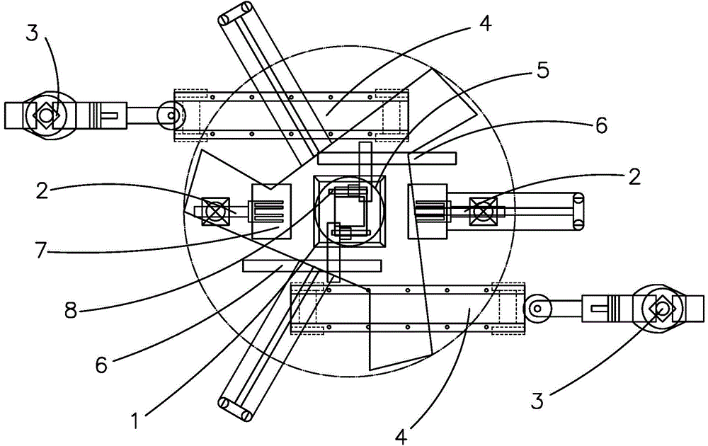
[0022] Such as figure 1 As shown, an OLED automatic binding device includes a base and a positioning base 1 located in the center of the base, and is installed around the positioning base 1:

[0023] Cylindrical coordinate robot 2: used to pick and place the IC tray 7 on the AGV (Automated Guided Vehicle, referred to as AGV) or the tray rack and place it on the abutment, such as figure 1 As shown, the rapid switching of the IC tray 7 is realized when the device is running, and placing it on the base is mainly to facilitate the operation of the DELTA robot and the cylindrical coordinate robot at the same time.

[0024] Multi-joint robot 3: used to take out the OLED device from the cassette and place it on the transfer device 4 or pick up the OLED de...


PUM


Abstract

The invention discloses an OLED automatic binding device which comprises a cylindrical coordinate robot used for taking or placing the IC tray on the AGV or tray shelf; a multi-joint robot used for taking the OLED device from a clamping box and placing the OLED device on a transmission device or taking OLED device from the transmission device and placing the OLED device into the clamping box; a DELTA robot used for taking OLED device from the transmission device and placing the OLED device on a vacuum absorbing work table, or taking the bound device from the vacuum absorbing work table and placing the device on the transmission device; the DELTA robot is further used for taking the IC from the IC tray and placing the IC at the pointed place; the vacuum absorbing work table used for absorbing and fixing the OLED device; and a orthogonal coordinate robot used for binding the IC on the OLED device. The OLED automatic binding device can bind the OLED device and the IC automatically; the binding device is combined with the factory automatic system for improving the production efficiency of the whole production line and the compatibility of the manufacture information.

Description

technical field [0001] The invention belongs to the field of OLED display technology, in particular to an OLED automatic binding device. Background technique [0002] Organic Light-Emitting Diode (OLED), also known as Organic Light-Emitting Diode (OLED), was discovered in the laboratory by Chinese-American professor Deng Qingyun, and the research on OLED was launched. OLED display technology has the characteristics of self-illumination, using very thin organic material coating and glass substrate, these organic materials will emit light when current passes through, and the OLED display screen has a large viewing angle and can save power. [0003] OLED display technology has the characteristics of self-illumination, using very thin organic material coating and glass substrate. The whole structural layer includes: hole transport layer (HTL), light emitting layer (EL) and electron transport layer (ETL). When the power is supplied to an appropriate voltage, the positive holes ...

Claims


Application Information

Patent Timeline
IPC IPC(8): H01L51/56
CPCH05K13/022
Inventor 任海向欣
Owner SICHUAN CCO DISPLAY TECH
Learn More