
Dual-stator axial magnetic field flux switching type hybrid permanent magnet memory motor

An axial magnetic field and magnetic flux switching technology, applied in magnetic circuits, electrical components, electromechanical devices, etc., can solve the problems of large field weakening loss, difficult adjustment of air gap magnetic field, poor torque performance, etc., and achieve low field weakening loss. , the effect of large operating range and high power density

Active Publication Date: 2015-05-13
SOUTHEAST UNIV
View PDF5 Cites 9 Cited by
  • Summary
  • Abstract
  • Description
  • Claims
  • Application Information

AI Technical Summary

Problems solved by technology

The double salient pole structure of the traditional flux switching motor makes the cogging torque larger and the torque performance is poor
The flux switching motor adopts the stator permanent magnet structure. As a permanent magnet motor, there is also the problem that the air gap magnetic field is difficult to adjust.
When the motor is running at low speed and low torque, the iron consumption of the motor is large; when the motor is running at high speed, the traditional method uses direct-axis demagnetization current or a separate field-weakening winding to maintain the field-weakening operation, just like other types of permanent magnet motors , there is a problem of large weak magnetic loss

Method used


Image

  • Dual-stator axial magnetic field flux switching type hybrid permanent magnet memory motor
  • Dual-stator axial magnetic field flux switching type hybrid permanent magnet memory motor
  • Dual-stator axial magnetic field flux switching type hybrid permanent magnet memory motor

Examples


Embodiment Construction

[0017] The present invention will be further described below in conjunction with the accompanying drawings.

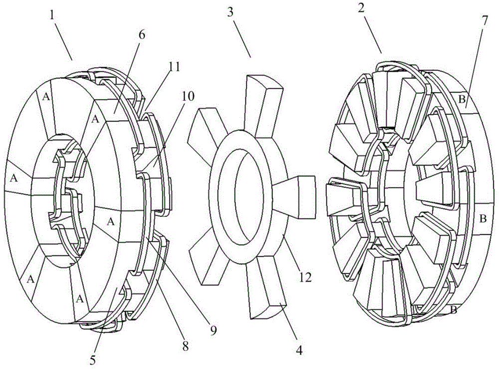
[0018] like figure 1 Shown is a dual-stator axial field flux switching type hybrid permanent magnet memory motor, including a first stator 1, a second stator 2 and a rotor 3; the first stator 1, the second stator 2 and the rotor 3 all adopt Salient poles, and the two stators have the same structure and are located opposite to each other; the rotor 3 is coaxially arranged between the two stators;

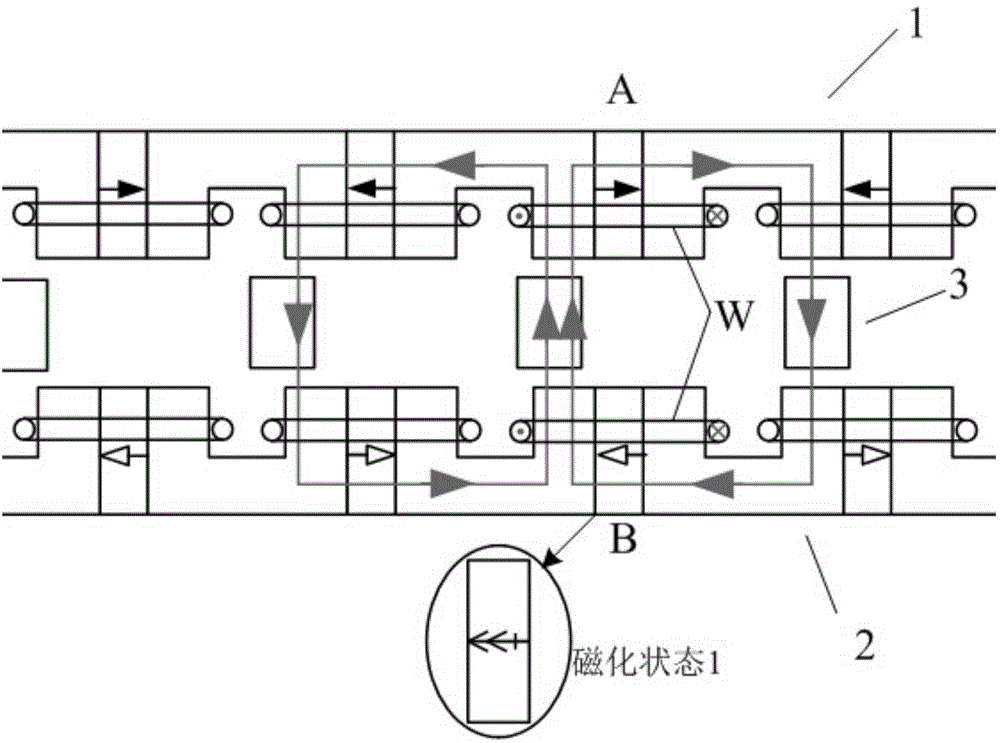
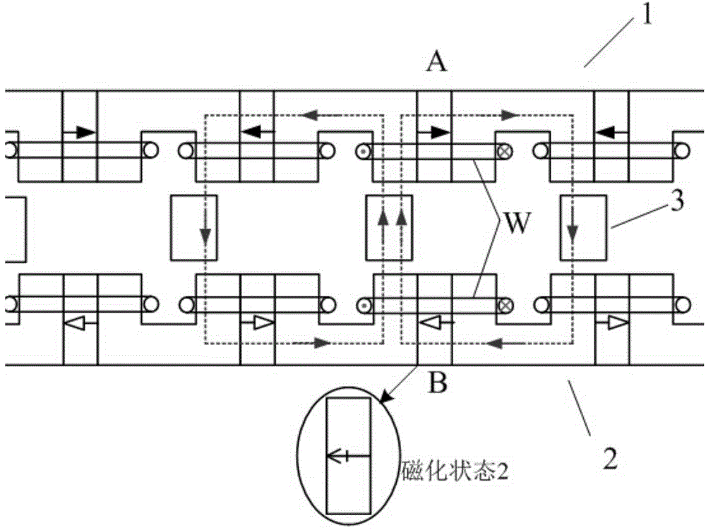
[0019] The stator includes 6n U-shaped magnetically conductive cores 5, and the 6n U-shaped magnetically conductive cores 5 are evenly arranged to form a circular ring. There is a gap; the gap is divided into two sections along the axial direction, and the permanent magnet is next to the U-shaped magnetic core 5 and embedded in a section close to the stator yoke; all the gaps in the first stator 1 are provided with high-coercivity permanent magnet neodymium Iron boron 6, na...


PUM


Abstract

The invention discloses a dual-stator axial magnetic field flux switching type hybrid permanent magnet memory motor. The dual-stator axial magnetic field flux switching type hybrid permanent magnet memory motor comprises two salient pole stators and a salient pole rotor. The two stators are of the same structure and named as a first stator and a second stator which are arranged at opposite positions. The rotor is coaxially disposed between the two stators. One of the two stators is made of a neodymium iron boron permanent magnet and the other stator is made of an aluminum nickel cobalt permanent magnet. The permanent magnet of each of the two stators is alternately magnetized in the circumferential direction. The magnetization directions of the permanent magnets of the two stators at relative opposite positions are opposite. The two permanent magnets are in series connection in a magnetic circuit. The stator made of the neodymium iron boron permanent magnet is used for generating constant flux. The stator made of the aluminum nickel cobalt permanent magnet is used for generating variable flux for adjusting an air-gap magnetic field. The dual-stator axial magnetic field flux switching type hybrid permanent magnet memory motor provides an excitation mode of hybrid permanent magnet of a series structure and has the advantages of maintaining high power density of a traditional permanent magnet motor and being wide in rotation speed running range and high in efficiency of a memory motor.

Description

technical field [0001] The invention relates to a dual-stator axial magnetic flux switching type hybrid permanent magnet memory motor. Background technique [0002] Due to its high power density, high efficiency, and simple structure, permanent magnet synchronous motors have been widely used in industry, aerospace and other fields. However, due to the limitation of the characteristics of the permanent magnet material itself, the traditional permanent magnet motor has the problems that the air gap magnetic field is difficult to adjust and it is difficult to achieve a wide speed range. With the development of permanent magnet materials and permanent magnet motors, more and more household appliances and electric vehicles are driven by permanent magnet motors. The motors in these devices generally run at variable speeds. When they run at low speed and low torque, the iron consumption is large. When running at high speed, due to the limitation of the inverter voltage, the magnet...

Claims


Application Information

Patent Timeline
IPC IPC(8): H02K16/04
CPCH02K1/143H02K1/17H02K1/243H02K16/04H02K2201/06
Inventor 林明耀李念郝立徐妲付兴贺
Owner SOUTHEAST UNIV
Learn More