Solar power generation device capable of automatically removing snow and dust

A power generation device and solar energy technology, which is applied in the direction of photovoltaic power generation, electrical components, and the support structure of photovoltaic modules, etc., can solve problems such as unsatisfactory dust removal, damage to photovoltaic modules, and greater impact on the safety of photovoltaic module structures, and achieve good dust and snow removal effects , small safety impact, wide application effect

Active Publication Date: 2015-05-13
江苏明敏科技有限公司
View PDF8 Cites 24 Cited by
  • Summary
  • Abstract
  • Description
  • Claims
  • Application Information

AI Technical Summary

Problems solved by technology

The invention patent application uses the spring and cam mechanism to control the vibrating inertial motion of the photovoltaic module to remove dust and snow. Because the vibration amplitude cannot be too large, it can only remove the thicker dust (snow) on the surface of the ba

Method used


Image

  • Solar power generation device capable of automatically removing snow and dust
  • Solar power generation device capable of automatically removing snow and dust
  • Solar power generation device capable of automatically removing snow and dust

Examples


Embodiment 1

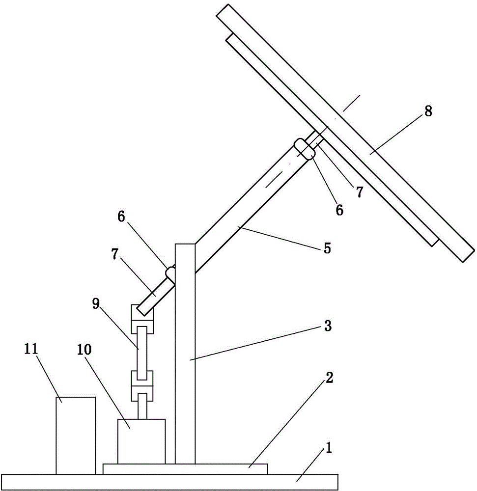
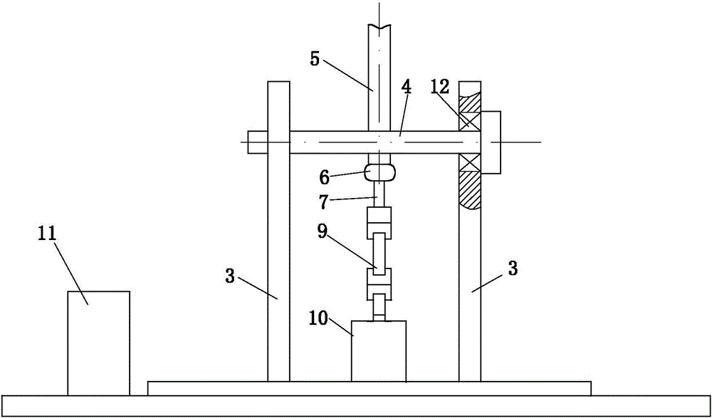
[0018] See figure 1 and image 3 , this embodiment has a solar photovoltaic module 8 , a base 1 and a rotating unit 2 installed on the base 1 . The solar photovoltaic module 8 has photovoltaic panels. A motor 10 and two uprights 3 are installed on the rotating unit 2 , a rotatable support shaft 4 is arranged between the two uprights 3 , and both ends of the support shaft 4 are respectively connected with the corresponding uprights 3 through bearings 12 . A sleeve 5 perpendicular thereto is fixed on the support shaft 4, and a rotating shaft 7 is arranged in the sleeve 5, and the rotating shaft 7 is supported by two bearings 6 arranged at the upper and lower ends of the sleeve 5 respectively. The solar photovoltaic module 8 is fixed on the upper end of the rotating shaft 7 , and a telescopic double-cross universal joint 9 is connected between the lower end of the rotating shaft 7 and the output shaft of the motor 10 . Telescopic double cross-shaft universal joint 9 can be pur...

Embodiment 2

[0022] See Figure 4 , this embodiment has a solar photovoltaic module 8 and a base 1 . The solar photovoltaic module 8 has photovoltaic panels. A motor 10 and two columns 3 are installed on the base 1 , and a support shaft 4 is arranged between the two columns 3 . A sleeve 5 perpendicular thereto is fixed on the support shaft 4, and a rotating shaft 7 is arranged in the sleeve 5, and the rotating shaft 7 is supported by two bearings 6 arranged at the upper and lower ends of the sleeve 5 respectively. The solar photovoltaic module 8 is fixed on the upper end of the rotating shaft 7 , and a telescopic double-cross universal joint 9 is connected between the lower end of the rotating shaft 7 and the output shaft of the motor 10 . Telescopic double cross-shaft universal joint 9 can be purchased from the market. An electrical control box 11 is arranged on the base 1 , and the operation of the motor 10 is controlled by the electrical control box 11 . The angle α at which the rot...


PUM


Abstract

Disclosed is a solar power generation device capable of automatically removing snow and dust. The solar power generation device capable of automatically removing snow and dust comprises a solar photovoltaic module, a base and a rotating unit mounted on the base. The rotating unit is provided with a motor and two vertical columns; a rotatable support shaft is arranged between the two vertical columns and fixedly provided with a sleeve perpendicular to the support shaft; a rotating shaft is arranged inside the sleeve and born by two bearings at the upper end and the lower end of the sleeve; the solar photovoltaic module is fixed at the upper end of the rotating shaft; a telescopic double-cross axle type universal coupler is connected between the lower end of the rotating shaft and the output shaft of the motor. The solar power generation device capable of automatically removing snow and dust can simulate the turning actions of living beings and eliminate snow and dust on a photovoltaic battery panel through centrifugal force generated by forward and reverse rotation of the photovoltaic battery panel, thereby obtaining high snow removing effects. Compared with vibration type dust removal, the solar power generation device capable of automatically removing snow and dust has small or even no influence on structural safety of the photovoltaic module, thereby avoiding damage to the photovoltaic module as much as possible. Compared with contact type dust removal, the solar power generation device capable of automatically removing snow and dust avoids the problem of abrasion on the surface of the photovoltaic battery panel.

Description

technical field [0001] The present invention relates to a solar power generation device. Background technique [0002] The areas with relatively sufficient solar energy resources in my country are generally concentrated in the high-altitude areas in the west. Due to sufficient sunshine and less rainfall in these places, the photovoltaic panels in solar power generation devices are more likely to accumulate dust. In addition, in high-altitude areas, the snowfall in winter is relatively sufficient and the snow is difficult to melt, which will damage the battery. The panels receive sunlight and cause obstacles. When the accumulation of sand, dust and snow on the battery board reaches a certain level, it will have a significant impact on the power generation efficiency of the battery board and cause damage to the battery board. [0003] The utility model of Chinese patent application No. 200720036270.3 discloses a dust removal device for solar power generation panels. A hoist ...

Claims


Application Information

Patent Timeline
IPC IPC(8): H02S40/10H02S40/12H02S20/32
CPCH02S20/00H02S40/00Y02E10/50
Inventor 毕玉春汪小锋陈连玉
Owner 江苏明敏科技有限公司
Why Eureka
Try Eureka