Stamping die shank

A technology of stamping die and die handle, which is used in forming tools, manufacturing tools, metal processing equipment, etc., can solve the problems of reducing the traction performance of the die handle, easy to loosen, etc., so as to improve the connection stability, prevent the loosening phenomenon, and improve the traction. performance effect

Inactive Publication Date: 2015-05-20
HEFEI MAILI NETWORK TECH
View PDF0 Cites 0 Cited by
  • Summary
  • Abstract
  • Description
  • Claims
  • Application Information

AI Technical Summary

Problems solved by technology

However, when the mold handle in the prior art is installed on the upper template, it is easy to loosen, because the mold handle is connected to the press and the upper template, which reduces the traction performance of the mold handle

Method used


Image

  • Stamping die shank

Examples


Embodiment Construction

[0011] In order to make the object, technical solution and advantages of the present invention clearer, the present invention will be further described in detail below in conjunction with the accompanying drawings and embodiments. It should be understood that the specific embodiments described here are only used to explain the present invention, not to limit the present invention.

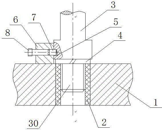
[0012] see figure 1 , figure 1 It is a structural schematic diagram of the present invention.

[0013] The die handle of a stamping die includes an upper template 1 and a die handle 3, a die sleeve 2 is fixedly installed in the die handle mounting hole of the upper template 1, and a threaded connection section 30 is provided below the die handle 3, The mold handle 3 is threadedly connected with the mold sleeve 2; one side of the mold handle 3 is provided with a slanted slot 5, and the upper end of the upper template 1 is fixedly connected with a stopper 6, and the stopper 6 is provided with a...


PUM


Abstract

The invention relates to a stamping die shank. The stamping die shank comprises an upper die plate and a die shank body. A die sleeve is fixedly installed in a die shank installation hole of the upper die plate, a threaded connection section is arranged on the lower portion of the die shank body, and the die shank body is in threaded connection with the die sleeve; an inclined notch is formed in one side face of the die shank body, a stop block is fixedly connected to the upper end of the upper die plate, a screw installation hole corresponding to the inclined notch is formed in the stop block, a pin used for abutting against the inclined notch is installed in the screw installation hole and connected with a screw, and an elastic pad is arranged on the connecting face between the die shank body and the upper die plate. Pressure of a press machine is transmitted to the upper die plate through the die shank body; because the upper die plate is in threaded connection with the die shank body, loosening can be effectively prevented; meanwhile, because the screw and the pin are additionally arranged on the side face and can abut against the inclined notch, connecting stability is further improved, and the traction performance of the die shank body is improved.

Description

technical field [0001] The invention relates to the field of stamping die parts, in particular to a stamping die handle. Background technique [0002] The cold stamping process is an advanced processing method with high production efficiency, less cutting or no cutting, and has many advantages in economy and technology. It is easy to operate, easy to realize mechanization and automation, and is suitable for the production of larger batches of parts. Its products generally do not require further machining, and their dimensional accuracy and interchangeability are also relatively good. Therefore, it occupies a very important position in industries such as aviation, automobiles, tractors, electrical appliances, and precision instruments. In stamping production, the stamping die, as a specific execution tool of the stamping process, naturally attracts attention. In fact, the design level and manufacturing accuracy of the stamping die structure are the key to ensuring the qu...

Claims


Application Information

Patent Timeline
IPC IPC(8): B21D37/10
CPCB21D37/10
Inventor 王宁
Owner HEFEI MAILI NETWORK TECH
Why Eureka
Try Eureka