Tin soldering jig and laser tin soldering method

A soldering and fixture technology, applied in the direction of manufacturing tools, welding equipment, auxiliary welding equipment, etc., can solve the problems of low welding quality and inconvenient operation of intensive soldering

Active Publication Date: 2015-05-20
HANS LASER TECH IND GRP CO LTD
View PDF10 Cites 7 Cited by
  • Summary
  • Abstract
  • Description
  • Claims
  • Application Information

AI Technical Summary

Problems solved by technology

[0004] The purpose of the embodiments of the present invention is to provide a soldering jig and a laser soldering method to solve the problems of inconvenient operation and low soldering quality in the existing intensive soldering

Method used


Image

  • Tin soldering jig and laser tin soldering method
  • Tin soldering jig and laser tin soldering method
  • Tin soldering jig and laser tin soldering method

Examples


Embodiment Construction

[0022] In order to make the object, technical solution and advantages of the present invention clearer, the present invention will be further described in detail below in conjunction with the accompanying drawings and embodiments. It should be understood that the specific embodiments described here are only used to explain the present invention, not to limit the present invention.

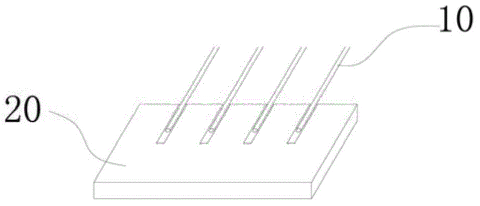
[0023] like figure 1 As shown, multiple cables 10 are densely arranged on the pad 20, and the cables 10 need to be welded on the pad 20 by means of welding. The distance between the multiple cables 10 is very small, and the discharge is dense. Due to the laser The energy of the tin is relatively high, but the solder joints of the tin are relatively low. When the laser welds one of the wires, it may cause the tin material on the soldered wire near the welding to melt again, and between multiple wires A connection is formed which eventually shorts out the flex wire.

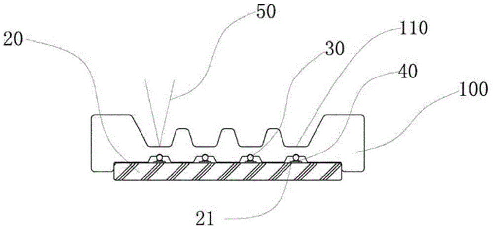
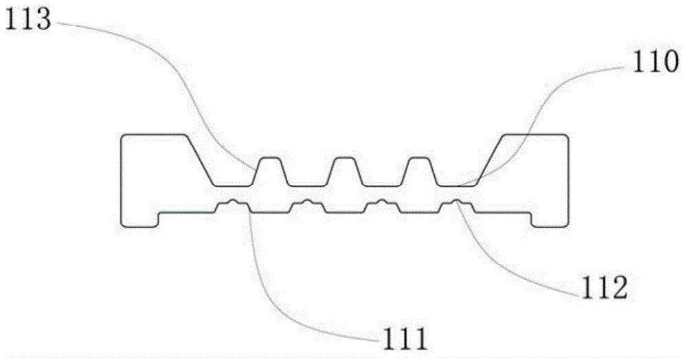
[0024] like figure 2 , 3 , ...


PUM


Abstract

The invention relates to the field of laser tin solder, and provides a tin soldering jig. Heat conduction portions are arranged on the tin solder jig at intervals and are made of heat conduction materials, when the tin soldering jig is arranged on a soldering pad, the heat conduction portions make contact with to-be-soldered portions of a to-be-soldered product and compress the to-be-soldered portions and tin materials on the soldering pad, laser heats the heat conduction portions in an illumination mode and transmits heat to the to-be-soldered portions and the tin materials making contact with the to-be-soldered portions, and the tin materials are melted. The laser does not directly heat the tin materials, heat is transmitted to the tin materials in a heat transmission mode, the to-be-soldered product is welded, and high energy generated when the laser directly irradiates the product is prevented from affecting the welding effect of other to-be-soldered portions. The embodiment of the invention further provides a laser tin soldering method.

Description

technical field [0001] The invention belongs to the field of laser welding, in particular to a soldering fixture and a laser soldering method. Background technique [0002] With the improvement of industrial manufacturing technology, electrical components such as data cables are developing towards high-density and high-reliability miniaturization. The spacing between various cables or pins is getting smaller and smaller. Traditional soldering iron welding, Connection methods such as reflow soldering have been difficult to meet their welding requirements. Laser soldering technology has the characteristics of local heating, less thermal damage to components, small heat-affected zone, non-contact heating, no need for other auxiliary tools, good repeatability, easy power control, high yield, easy automation, etc., and unique According to the characteristics of the light source, laser soldering has become the main welding method, and its welding process includes preset soldering...

Claims


Application Information

Patent Timeline
Patent Type & Authority Applications(China)
IPC IPC(8): B23K3/08B23K37/04B23K1/005
CPCB23K1/0056B23K3/087B23K37/04
Inventor 朱宝华胡学安高云峰
Owner HANS LASER TECH IND GRP CO LTD
Why Eureka
Try Eureka