Printing ribbon driving device

A driving device and a technology for printing ribbons, which are applied to inking devices, printing, etc., can solve the problems of entanglement of printing ribbons, poor processing performance, and high production costs, so as to reduce production costs, eliminate ribbon waste, and eliminate waste. Effect

Active Publication Date: 2015-05-20
王晨
View PDF9 Cites 13 Cited by
  • Summary
  • Abstract
  • Description
  • Claims
  • Application Information

AI Technical Summary

Problems solved by technology

[0003] However, the ribbon drive device of existing printers has problems such as complex structure, high cost of mechanism manufacturing, poor processing performance and difficult maintenance.
In addition, the card printer sometimes needs to rewind the ribbon to the ribbon supply shaft during use, but with the existing ribbon drive technology, the printing ribbon can only be wound forward

Method used


Image

  • Printing ribbon driving device
  • Printing ribbon driving device
  • Printing ribbon driving device

Examples


Embodiment 1

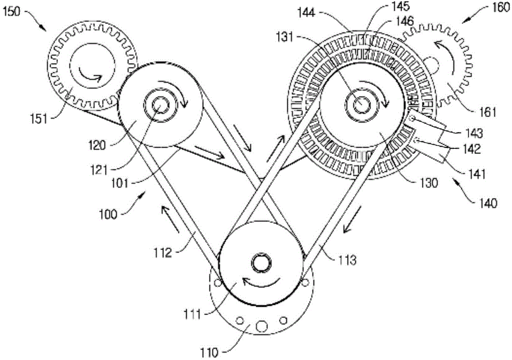
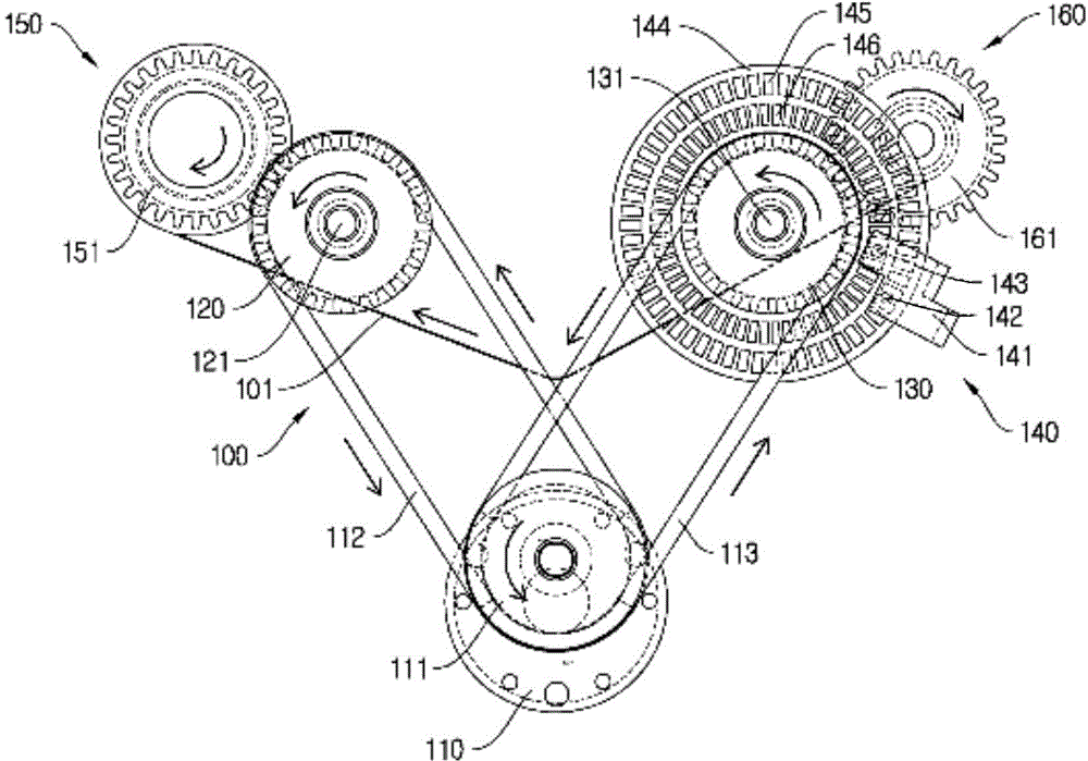
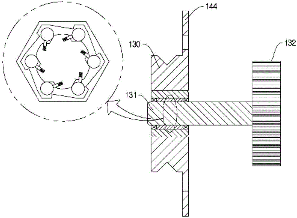
[0046] This embodiment provides a printing ribbon driving device, such as figure 1 , Figure 4 , Figure 5 As shown, the apparatus includes a ribbon supply shaft 150 , a ribbon take-up shaft 160 , a ribbon 101 and a drive 110 . The driver 110 is fixedly installed in the casing of the printer, and the output shaft of the driver 110 is fixedly installed with double driving pulleys 111 . Both the ribbon supply shaft 150 and the ribbon winding shaft 160 are rotatably installed in the housing of the printer through bearings, the ribbon supply shaft 150 and the ribbon winding shaft 160 are parallel to each other, and the ribbon 101 is wound around the ribbon supply shaft 150 and the ribbon winding shaft 160. The tape is wound on the shaft 160.

[0047] One end of the ribbon supply shaft 150 is fixedly mounted with a first driven gear 151, the first driven gear 151 is coaxially arranged with the ribbon supply shaft 150, the first driven gear 151 meshes with the first driving gear ...

Embodiment 2

[0067] The difference between this embodiment and Embodiment 1 is that the output shaft of the driver (two-way motor) is fixedly equipped with double drive pulleys, the ribbon supply shaft is equipped with the first pulley through the first one-way bearing, and the ribbon winding shaft The second pulley is installed through the second one-way bearing, the double drive pulley is connected with the first pulley through the first drive transmission belt, the double drive pulley is connected with the second pulley through the second drive transmission belt, and the outer ring of the first one-way bearing rotates clockwise , the inner ring can rotate freely, and it is locked when it rotates counterclockwise. When the outer ring of the second one-way bearing rotates counterclockwise, the inner ring can rotate freely, and it is locked when it rotates clockwise.

[0068] The ribbon sensor detection device is arranged at the first pulley, and the ribbon sensor detection device is used t...

Embodiment 3

[0070] The difference between this embodiment and Embodiment 1 is that the first gear is fixedly installed on the output shaft of the driver, the second gear is installed on the ribbon supply shaft through the first one-way bearing, and the ribbon winding shaft passes through the second one-way bearing. The third gear is installed on the bearing, and the second gear and the third gear are both meshed with the first gear. When the outer ring of the first one-way bearing rotates clockwise, the inner ring can rotate freely, and it is locked when it rotates counterclockwise. The second one-way bearing When the bearing outer ring is rotated counterclockwise, the inner ring can rotate freely, and when it is rotated clockwise, it is locked.

[0071] The ribbon sensor detection device is arranged at the third gear, and the ribbon sensor detection device is used to detect the rotation information of the third gear, and transmit the detected rotation information to the controller of the ...


PUM


Abstract

The invention discloses a printing ribbon driving device, which comprises a ribbon supplying shaft, a ribbon winding shaft, a ribbon and a drive, wherein the ribbon is wound on the ribbon supplying shaft and the ribbon winding shaft, the drive can positively and reversely rotate, when the drive drives the ribbon winding shaft to clockwise rotate, transmission does not exist between the drive and the ribbon supplying shaft, the ribbon supplying shaft rotates through being pulled by the ribbon, when the drive drives the ribbon supplying shaft to anticlockwise rotate, transmission does not exist between the drive and the ribbon winding shaft, and the ribbon winding shaft rotates through be pulled by the ribbon. The printing ribbon driving device has the advantages that the simultaneous execution of the identification card printer printing function and the ribbon winding function is realized through adopting one drive, and the ribbon control precision and the printer stability of products are greatly improved.

Description

technical field [0001] The invention relates to the field of printers, in particular to a printing ribbon driving device for a printer. Background technique [0002] As we all know, the card printer is a special printer dedicated to printing the surface information of various cards such as ID cards, ID cards, employee cards, and visitor cards. It uses cutting-edge dye-sublimation printing technology. The specific card printing process of the card printer is to supply the card from the card supply device (into the card slot), and after the card walks to the bottom of the dye-sublimation print head, the print head is pressed down, and then the YMCKO color belt that the customer wants to print can be overheated and sublimated. The information is printed on the surface of the PVC card and covered with a transparent protective film. In the state where the YMCKO color ribbon is wound on the ribbon supply shaft, the printed ribbon is wound to the winding shaft by the ribbon drivin...

Claims


Application Information

Patent Timeline
Patent Type & Authority Applications(China)
IPC IPC(8): B41J33/14
Inventor 苏义军
Owner 王晨
Why Eureka
Try Eureka