A truss-type steel transverse diaphragm of a corrugated steel web cable-stayed bridge

A corrugated steel web and truss-type technology, which is applied to cable-stayed bridges, truss bridges, bridge forms, etc., can solve problems such as poor torsional rigidity, and achieve the effects of cable force transmission, enhanced torsional rigidity, and easy implementation

Active Publication Date: 2016-06-15
ZHENGZHOU COMM PLANNING SURVEY & DESIGN INST
View PDF8 Cites 0 Cited by
  • Summary
  • Abstract
  • Description
  • Claims
  • Application Information

AI Technical Summary

Problems solved by technology

[0003] Compared with the traditional box girder cable-stayed bridge, the corrugated steel web cable-stayed bridge has lighter self-weight, but poorer torsional rigidity

Method used


Image

  • A truss-type steel transverse diaphragm of a corrugated steel web cable-stayed bridge
  • A truss-type steel transverse diaphragm of a corrugated steel web cable-stayed bridge
  • A truss-type steel transverse diaphragm of a corrugated steel web cable-stayed bridge

Examples


Embodiment 1

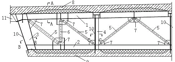
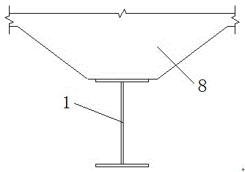
[0025] see attached figure 1 , figure 2 , image 3 and Figure 4 , The present invention provides a truss-type steel diaphragm of a corrugated steel web cable-stayed bridge, which includes an upper steel beam 1, a lower steel beam 2, an inclined web 3, a vertical web 4, an inclined web rod 5, and a vertical rod. 6 and the gusset plate 7; the top surface of the upper steel beam 1 is connected with the concrete of the box girder roof 8 through shear nails, and its two ends are welded to the steel anchor box 11 in the cable anchoring area, and the two ends of the upper steel beam 1 are anchored with the stay cables The steel anchor box in the area is welded to form a transverse force transmission system, which effectively realizes the transmission of cable force. 1. Between the lower steel beam 2, the upper steel beam 1 and the lower steel beam 2 form a box room structure, and a truss-type steel diaphragm is set at the anchorage area of ​​the cable-stayed cable and the main b...

Embodiment 2

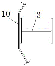
[0028] see attached figure 1 , figure 2 , image 3 and Figure 4 , The present invention provides a truss-type steel diaphragm of a corrugated steel web cable-stayed bridge, which includes an upper steel beam 1, a lower steel beam 2, an inclined web 3, a vertical web 4, an inclined web rod 5, and a vertical rod. 6 and the gusset plate 7; the top surface of the upper steel beam 1 is connected to the box girder top plate 8 concrete through shear nails, and both ends are welded to the steel anchor box 11 in the cable anchoring area, and the bottom surface of the lower steel beam 2 is connected to the box through shear nails. The beam bottom plate 9 is connected with concrete, and the corrugated steel web plate 10 is arranged between the upper steel beam 1 and the lower steel beam 2, and forms a box room structure with the upper steel beam 1 and the lower steel beam 2, and the inclined web 3 is connected to the vertical web. The upper and lower ends of the plate 4 are respecti...

Embodiment 3

[0031] see attached Figure 5 , The structural composition and construction process of the truss-type steel diaphragm are similar to those in Example 1, except that the beam height of the constant-section box girder is changed from 4.5m to 5.0m.

[0032] Technical effect analysis:

[0033] In order to further study the positive and beneficial effects of the present invention theoretically, taking a long-span corrugated steel web cable-stayed bridge as an example, two finite element models were established before and after the bridge was installed with truss-type steel diaphragms. Under the working conditions, the torsion angle of the main girder in the span of the two models is calculated, and its natural vibration characteristics are analyzed. The results show that the first-order transverse frequency of the bridge is increased by about 20% after the truss-type steel diaphragm is installed, and the torsion angle of the main girder in the middle of the bridge span is reduced ...


PUM


Abstract

The invention discloses a truss-type steel diaphragm plate of a corrugated steel web cable-stay bridge. An upper steel beam of the truss-type steel diaphragm plate is connected with concrete in the upper portion a top plate of a box beam through a shear stud. The two ends of the upper steel beam of the truss-type steel diaphragm plate are hinged to a steel anchor box in a cable anchor area. The bottom of a lower steel beam is connected with concrete in the lower portion of a bottom plate of the box beam through a shear stud. Corrugated steel webs are arranged between the upper steel beam and the lower steel beam. A box chamber structure is formed by enclosing the corrugated steel webs, the upper steel beam and the lower steel beam. The two ends of inclined webs and a vertical web are welded to the upper steel beam and the lower steel beam respectively. One sides of the inclined webs and the vertical web are connected with the corrugated steel webs in a welding mode. Due to the fact that inclined webs and a vertical rod are welded to gusset plates, the truss-type structure is formed by the inclined webs and the vertical rod. The truss-type steel diaphragm plate is arranged on a stayed-cable of the steel web cable-stay bridge and the main beam anchoring area, the horizontal connection of the corrugated steel web cable-stay bridge is enhanced, the torsional stiffness of a main beam is enhanced, the horizontal whole performance is effectively improved, the construction is convenient, the quality is guaranteed, and the bridge service life is prolonged.

Description

technical field [0001] The invention relates to the field of bridges, in particular to a truss-type steel diaphragm of a corrugated steel web cable-stayed bridge. Background technique [0002] Corrugated steel web cable-stayed bridge is a form of composite beam cable-stayed bridge, which consists of main tower, stay cables and PC composite box girder with corrugated steel web. The steel-concrete composite structure can give full play to the respective advantages of steel and concrete. By optimizing the combination of the two materials, they can give full play to their respective performance potentials, and achieve the goals of reducing construction costs, accelerating construction speed, and optimizing structural performance. The PC composite box girder with corrugated steel webs was invented by the French and developed rapidly in Japan. In recent years, many large-span PC composite box girder bridges with corrugated steel webs have also been built in my country. Compared w...

Claims


Application Information

Patent Timeline
Patent Type & Authority Patents(China)
IPC IPC(8): E01D19/00E01D19/16E01D11/04
CPCE01D6/00E01D11/04E01D2101/30
Inventor 惠涛赵圆圆陈萍时松李芳华陈猛张建勋郭理学冯焕杰黄明海李凯章陈斌张美丽武二杰闫丽霞张自雨毛登峰魏永强王鹏英周红梅谢芳芳
Owner ZHENGZHOU COMM PLANNING SURVEY & DESIGN INST
Why Eureka
Try Eureka