A roof and bottom shared underground structure and its separate construction method

A technology of underground structure and construction method, which is applied to underwater structures, infrastructure engineering, buildings, etc., can solve problems such as inapplicability of underground structures, large underground available space, and inapplicability of underground structures, so as to ensure construction safety, Save underground space and reduce construction difficulty

Inactive Publication Date: 2016-04-13
CHINA MERCHANTS CHONGQING COMM RES & DESIGN INST
View PDF5 Cites 0 Cited by
  • Summary
  • Abstract
  • Description
  • Claims
  • Application Information

AI Technical Summary

Problems solved by technology

[0007] The above two structural forms have certain limitations. Although the construction of the double-layer tunnel structure is not difficult, it has strict requirements on the construction time and sequence, and is not suitable for underground structures that will be added or built separately in the later stage; Although the superimposed (overlapping) tunnel structure can realize separate construction, it requires a large underground space available during construction. At the same time, the overall construction is difficult and the cycle is long, which is not suitable for some small spaces that require separate construction. underground structure

Method used


Image

  • A roof and bottom shared underground structure and its separate construction method
  • A roof and bottom shared underground structure and its separate construction method
  • A roof and bottom shared underground structure and its separate construction method

Examples


Embodiment Construction

[0037] The preferred embodiments of the present invention will be described in detail below with reference to the accompanying drawings.

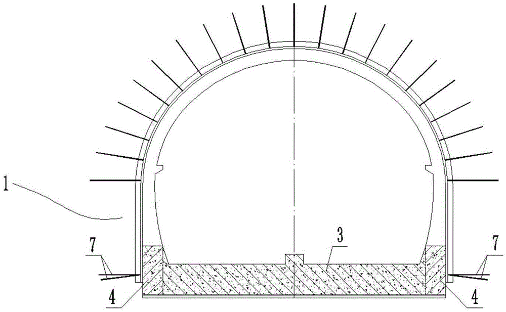
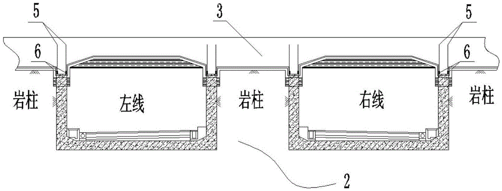
[0038] As shown in the figure, the top and bottom shared underground structure in this embodiment includes an upper structure 1, a lower structure 2 and a partition 3 arranged between the upper and lower structures for the two-layer structure. The upper structure 1 and the lower structure 2 Orthogonal arrangement, the upper structure 1 is a curved wall arch structure with a flat bottom; the lower structure 2 is a separated double-span rectangular frame structure, and the upper structure 1 has side wall feet and partitions 3 There are hidden beams 4 corresponding to each other, and the partitions 3 and the lower rectangular frame structure are fastened by steel bars. Specifically, the superstructure 1 is an arched flat-bottomed island-type station structure with five-center garden curved walls, and the substructure 2 is a separated double-sp...


PUM


Abstract

The invention discloses a top and bottom shared underground structure and a separated construction method of the top and bottom shared underground structure. The top and bottom shared underground structure comprises an upper-layer structure, a lower-layer structure and a partition board arranged between the upper-layer structure and the lower-layer structure and shared by the upper-layer structure and the lower-layer structure. The upper-layer structure and the lower-layer structure are arranged in an orthogonal mode. The upper-layer structure is of a curved wall arch structure, and the bottom of the upper-layer structure is in a flat bottom form. The lower-layer structure is of a separated double-span rectangular frame structure. Hidden beams are correspondingly arranged between the feet of side walls on the two sides of the upper-layer structure and the partition board. The partition board and the lower-layer rectangular frame structure are fastened through reinforcing steel bars. The top and bottom shared separated construction underground structure can be constructed by stages, that is, the upper-layer structure can be constructed in advance and opened to traffic, and then the lower-layer structure is constructed, so that the mutual influence is little; the top and bottom shared underground structure is applicable to the situation that the planning time and the construction starting time of different urban underground lines are arranged according to a sequential order; meanwhile, narrow urban underground space is effectively utilized, and the top and bottom shared underground structure can be constructed in a complex urban environment and is little in environmental influence and low in construction cost.

Description

technical field [0001] The invention belongs to the field of tunnel engineering, and in particular relates to an underground structure shared by the top and the bottom and a separate construction method thereof. Background technique [0002] Due to the excessive density of urban development, the available underground space is becoming increasingly narrow, and in many large cities, multiple traffic tunnels or underground structures have crossed, crossed, and overlapped within a limited space. The main structural forms in the prior art are as follows: [0003] (1) Double-layer tunnel structure [0004] The structure is further divided into two types: one is a large-diameter shield tunnel that is common in China, that is, two upper and lower layers of traffic lanes are set in a single tunnel. During the actual construction, the shield machine is used to assemble the tunnel shell structure according to the designed segments at one time, and then the diaphragm is installed insi...

Claims


Application Information

Patent Timeline
Patent Type & Authority Patents(China)
IPC IPC(8): E02D29/045
Inventor 郭军吴胜忠肖博吴梦军丁浩
Owner CHINA MERCHANTS CHONGQING COMM RES & DESIGN INST
Why Eureka
Try Eureka