A support structure of latitude and longitude foundation pit

A foundation pit support, warp and weft technology, applied in infrastructure engineering, excavation, construction, etc., can solve the problems of ineffective use of lateral stiffness, unfavorable stability of foundation pit, waste of support structure resistance, etc., and achieve wide application The effect of market and development prospects, improvement of integrity and stability, and saving of underground space

Active Publication Date: 2017-12-01
周霜林 +2
View PDF9 Cites 0 Cited by
  • Summary
  • Abstract
  • Description
  • Claims
  • Application Information

AI Technical Summary

Problems solved by technology

The existing support structure only utilizes the normal stiffness (relative to the foundation pit wall) of the row of piles, but the lateral stiffness has not been effectively utilized;
[0005] 3. Many foundation pit accidents show that only part of the piles fail when the foundation pit loses stability
At this time, if the row of piles is divided into three parts: the unstable pile, the implicated pile and the stable pile, the force transmitted from the crown beam and the waist beam to the implicated pile is still dominated by the normal (relative to the foundation pit) force, which is not conducive to The foundation pit is stable; while the stable piles cannot play a restrictive role for the unstable piles and the implicated piles, wasting part of the resistance of the supporting structure

Method used


Image

  • A support structure of latitude and longitude foundation pit
  • A support structure of latitude and longitude foundation pit
  • A support structure of latitude and longitude foundation pit

Examples


Embodiment Construction

[0024] The present invention will be further described below in conjunction with the accompanying drawings and specific embodiments thereof. The schematic embodiments and descriptions of the present invention are used to explain the present invention, but not as a limitation to the present invention.

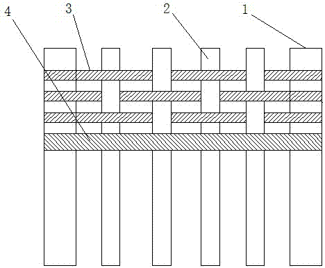
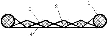
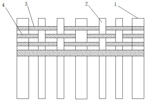
[0025] Such as figure 1 , figure 2 As shown, a latitude and longitude foundation pit support structure of this embodiment includes several rows of piles arranged in the foundation pit. The piles are composed of main piles 1 and auxiliary piles 2. In this embodiment, two main piles are set 1. The auxiliary piles 2 are distributed between the two main piles 1. The outer walls of the auxiliary piles 2 and the main piles 1 are arranged on the same plane. Both the main piles 1 and the auxiliary piles 2 are cylindrical, and the diameter and stiffness of the main pile 1 are equal. It is larger than the auxiliary pile 2, and also includes the main cable 4 and the auxiliary cable 3. Th...


PUM


Abstract

The invention discloses a warp and weft type foundation pit supporting structure. The warp and weft type foundation pit supporting structure comprises a plurality of row piles arranged in a foundation pit, auxiliary cables and main cables for applying prestress, wherein the row piles include main piles and auxiliary piles, the main piles and the auxiliary are distributed in an I-shaped manner, a plurality of auxiliary piles are distributed between every two adjacent main piles, the auxiliary piles and the outer walls of the main piles are arranged on the same plane, the main piles and the auxiliary piles are connected with the auxiliary cables in a warp and weft weaving manner, one main cable is connected between every two adjacent main piles, and the main cable contacts with the outer walls of the auxiliary piles between the main piles. Compared with the prior art, the warp and weft type foundation pit supporting structure has the advantages that the lateral rigidity of the overall row piles is fully utilized, the normal (relative to the wall of the foundation pit) deformation of the row piles is resisted through cable force transmission, the diameters and embedding depths of the row piles are reduced, the integrity and stability of the foundation pit support structure are increased, underground space is saved greatly, and the structure is promising in application market and development prospects.

Description

technical field [0001] The invention relates to the technical field of geotechnical engineering, in particular to a latitude and longitude foundation pit support structure. Background technique [0002] The existing foundation pit support usually adopts the method of row piles and anchor cables, and a good support effect has been achieved. However, this method has the following major problems: [0003] 1. The underground space occupied by the anchor cable is relatively large. With the massive development and utilization of underground space (such as subways, pipelines, etc.), there are more and more foundation pits that cannot meet the space requirements for anchor cable construction; [0004] 2. For a row of piles with uniform reinforcement, the stiffness in all directions around the pile body is the same. The existing support structure only utilizes the normal stiffness (relative to the foundation pit wall) of the row of piles, but the lateral stiffness has not been effe...

Claims


Application Information

Patent Timeline
Patent Type & Authority Patents(China)
IPC IPC(8): E02D17/04
CPCE02D17/04
Inventor 周霜林李铮肖军邓林杨赛舟陈昆萍李雨霖李庆达丁建军彭毅王刚
Owner 周霜林
Why Eureka
Try Eureka