Method for detecting and monitoring grouting material by utilizing conductivity difference

A technology of grouting materials and electrical conductivity, applied in the field of grouting materials, can solve problems such as the inability to grasp the grouting situation, the number of drills, the limited location, and the impact on the final grouting quality, so as to achieve high practical value and promotion value, and improve resource utilization. , The effect of low construction cost

Inactive Publication Date: 2020-08-25
胡瑾 +1
View PDF8 Cites 0 Cited by
  • Summary
  • Abstract
  • Description
  • Claims
  • Application Information

AI Technical Summary

Problems solved by technology

The traditional grouting inspection is to drill the field samples after grouting, use the laboratory to do the strength test and observe the grouting quality; firstly, it is impossible to carry out real-time monitoring of the construction process, and at the same time, only fixed-point inspections can be carried out on the inspection points, and, The number and location of drilling are limited, and the later detection method is also time-consuming and expensive, and it is impossible to grasp the comprehensive grouting situation
Not only that, after drilling and coring, the drilling point needs to be grouted twice to seal the drill hole, and the quality of the hole sealing will also affect the final grouting quality
In the grouting detection and monitoring, the number of drilled field samples is very large. Since the flow direction of the grouting material, the direction and width of the cracks are unknown after the grouting is poured, the traditional drilling Detection and monitoring is blind, and it is very likely to cause the area to be grouted to be riddled with holes. In this way, the workload of detection and monitoring is large, and the original geological conditions are seriously damaged

Method used


Image

  • Method for detecting and monitoring grouting material by utilizing conductivity difference
  • Method for detecting and monitoring grouting material by utilizing conductivity difference
  • Method for detecting and monitoring grouting material by utilizing conductivity difference

Examples


Embodiment

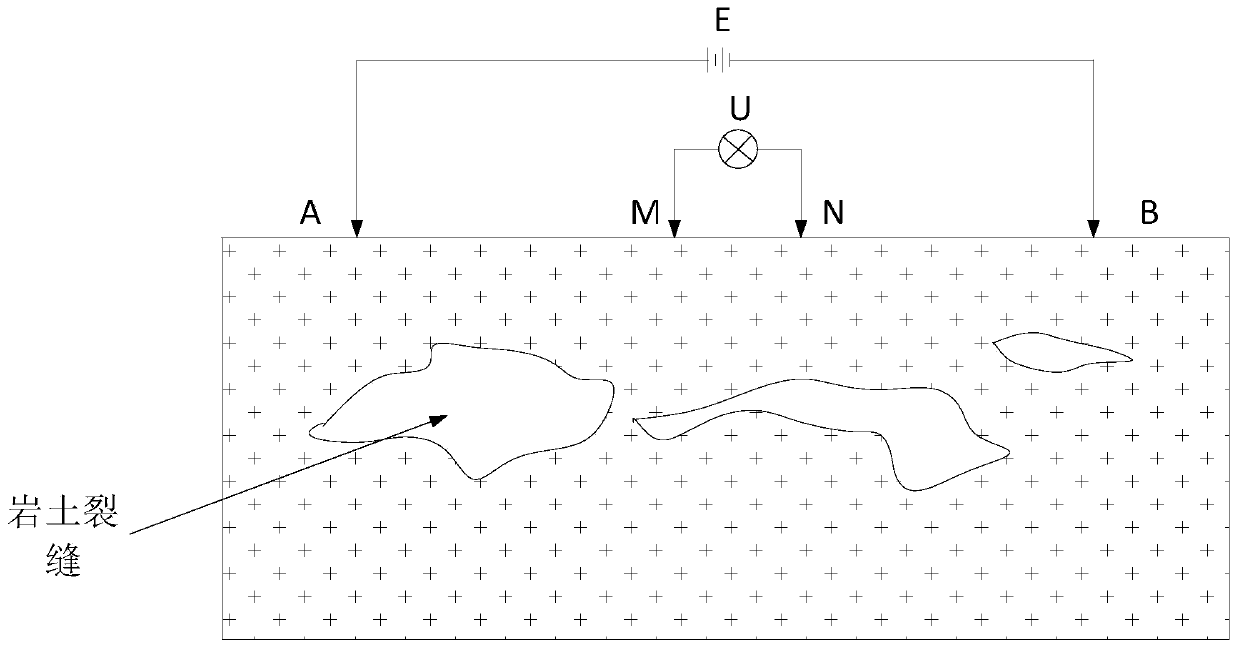
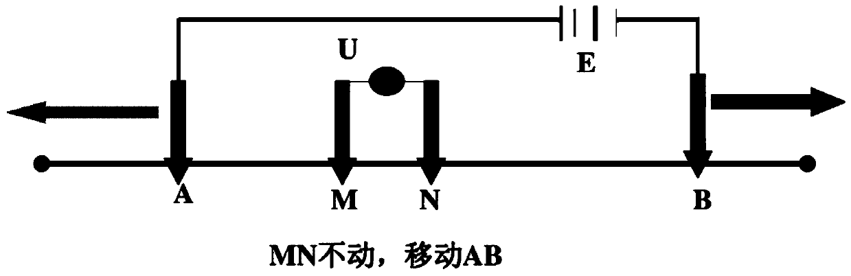
[0026] like Figure 1 to Figure 4 As shown, this embodiment provides a method for detecting and monitoring grouting materials utilizing differences in electrical conductivity, including the following steps:

[0027] In the first step, several electrodes are pre-embedded in the area to be grouted; in this embodiment, the depth of the pre-embedded electrodes is much lower than the depth of drilling, and it can not only provide quality inspection after grouting, but also provide The testing of the durability of grouting materials provides guarantee.

[0028] In the second step, the original resistance value of the area to be grouted is obtained by using the electrode method.

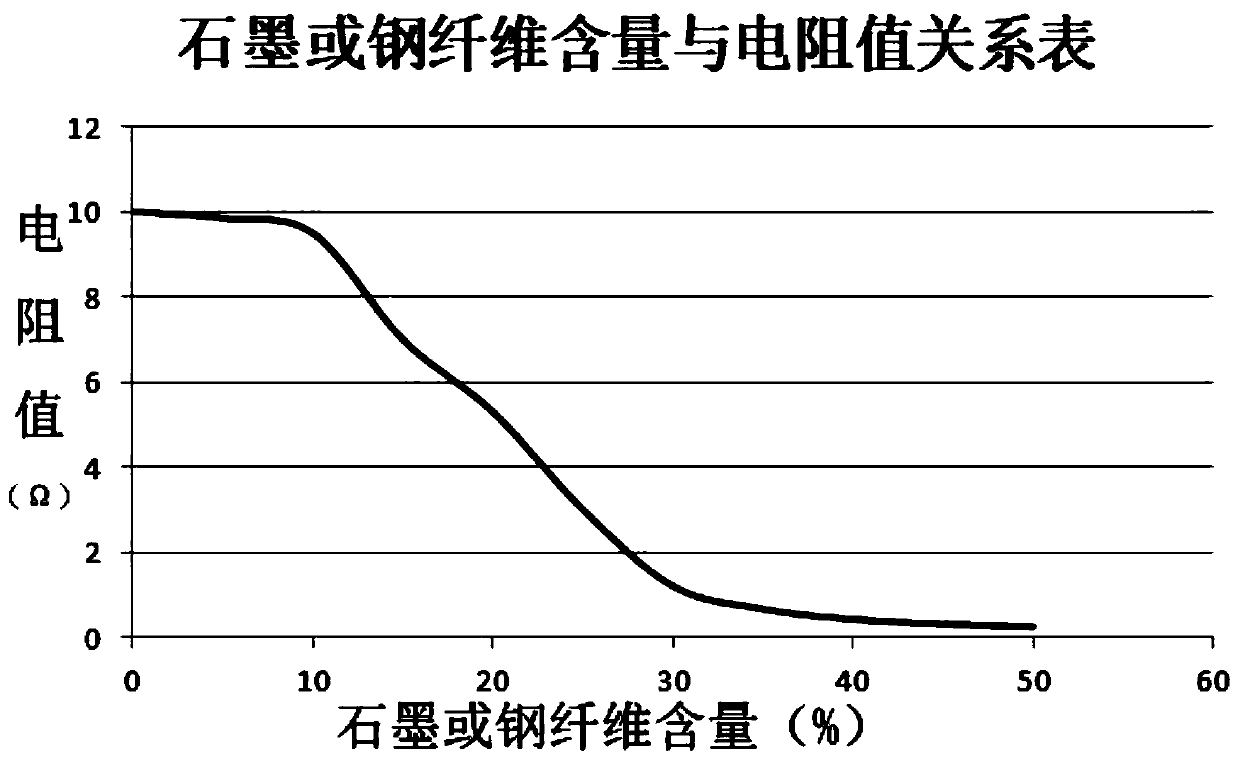
[0029] The third step is to adjust the type and proportion of the conductive material in the grouting material that utilizes the difference in electrical conductivity according to the original resistance value, and perform grouting in the area to be grouted; for example, in the grouting area of ​​a certain...


PUM


Abstract

The invention discloses a method for detecting and monitoring a grouting material by utilizing conductivity difference. The method comprises the following steps: pre-burying a plurality of electrodesin a to-be-grouted area; solving an original resistance value of a to-be-grouted area by adopting an electrode method; according to the original resistance value, adjusting the type and the proportionof the conductive performance changing material in the grouting material, and carrying out grouting pouring on the to-be-grouted area; and obtaining the current resistance after grouting through an electrode method, if the original resistance value is the same as or infinitely close to the current resistance value, determining that no grouting material exists in the area, and otherwise, determining that the area contains the grouting material. By means of the scheme, the method has the advantages of being low in cost, high in resource utilization rate, easy and convenient to detect and the like, and has high practical value and promotional value in the technical field of grouting materials.

Description

technical field [0001] The invention relates to the technical field of grouting materials, in particular to a detection and monitoring method for grouting materials utilizing differences in electrical conductivity. Background technique [0002] The grouting detection and monitoring process described in this article can be used in various environments suitable for grouting. The grouting effect and quality inspection is to detect the grouting filling after grouting and whether it meets the physical and mechanical properties of the design requirements. The traditional grouting inspection is to drill the field samples after grouting, use the laboratory to do the strength test and observe the grouting quality; firstly, the real-time monitoring of the construction process cannot be carried out, and at the same time, only fixed-point inspections can be carried out on the inspection points, and, The number and location of drilling are limited, and the later detection method is also ...

Claims


Application Information

Patent Timeline
Patent Type & Authority Applications(China)
IPC IPC(8): G01N27/07C04B14/38C04B14/48C04B14/00C04B18/04C04B22/00
CPCC04B14/024C04B14/46C04B14/48C04B18/04C04B22/002G01N27/07Y02W30/91
Inventor 胡瑾王向鹏
Owner 胡瑾
Why Eureka
Try Eureka