Continuous control mechanism

A control mechanism and continuous technology, which is applied in mechanical equipment, combustion engines, machines/engines, etc., can solve the problem that the volume of the intake pipe cannot be continuously variable, and achieve the effect of simple structure, reasonable design, and continuously variable volume

Inactive Publication Date: 2015-05-20
储德新
View PDF0 Cites 1 Cited by
  • Summary
  • Abstract
  • Description
  • Claims
  • Application Information

AI Technical Summary

Problems solved by technology

[0003] After searching the existing literature, it is found that the patent application number is 20142022823.6, and the patent technology named variable intake manifold for small displacement engines provides a two-stage variable exhaust pipe volume technology, but it cannot Continuously variable reality

Method used


Image

  • Continuous control mechanism
  • Continuous control mechanism
  • Continuous control mechanism

Examples


Embodiment

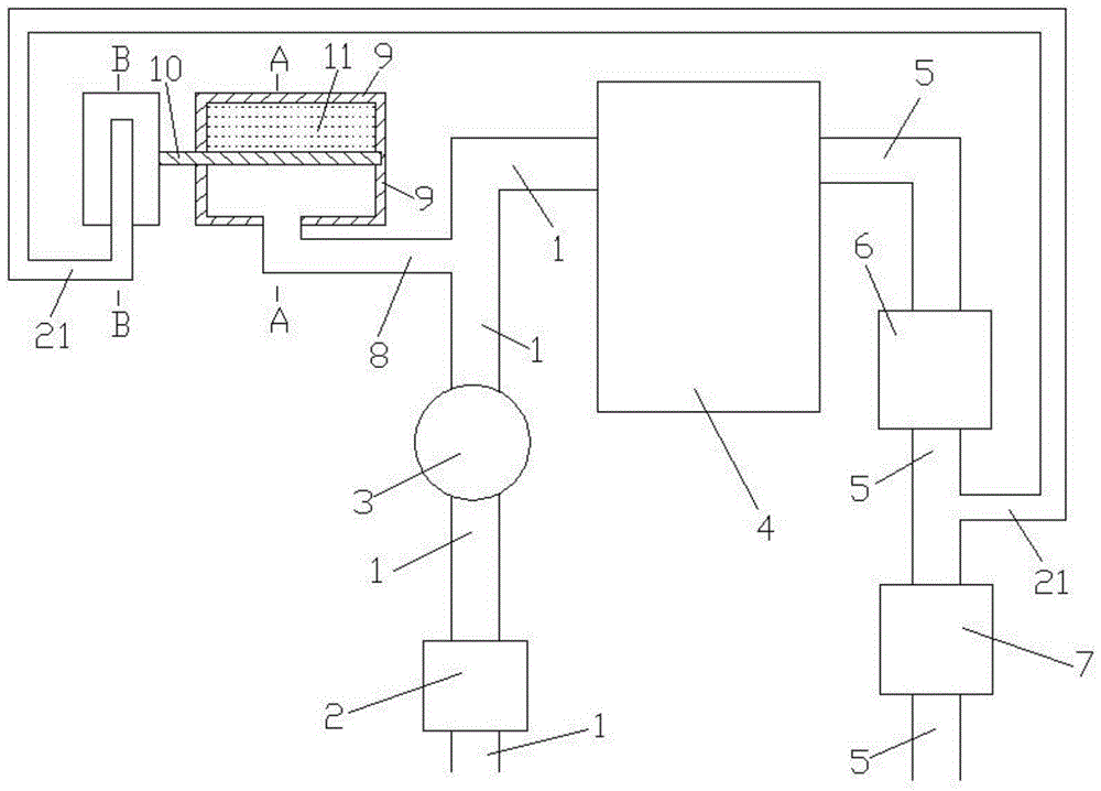
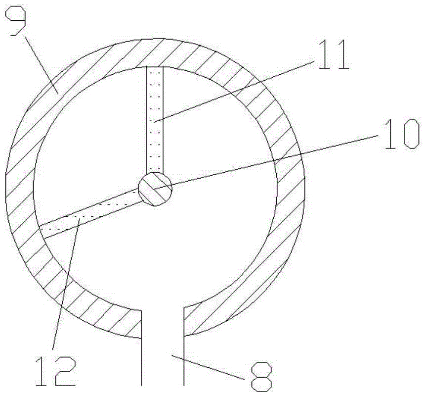
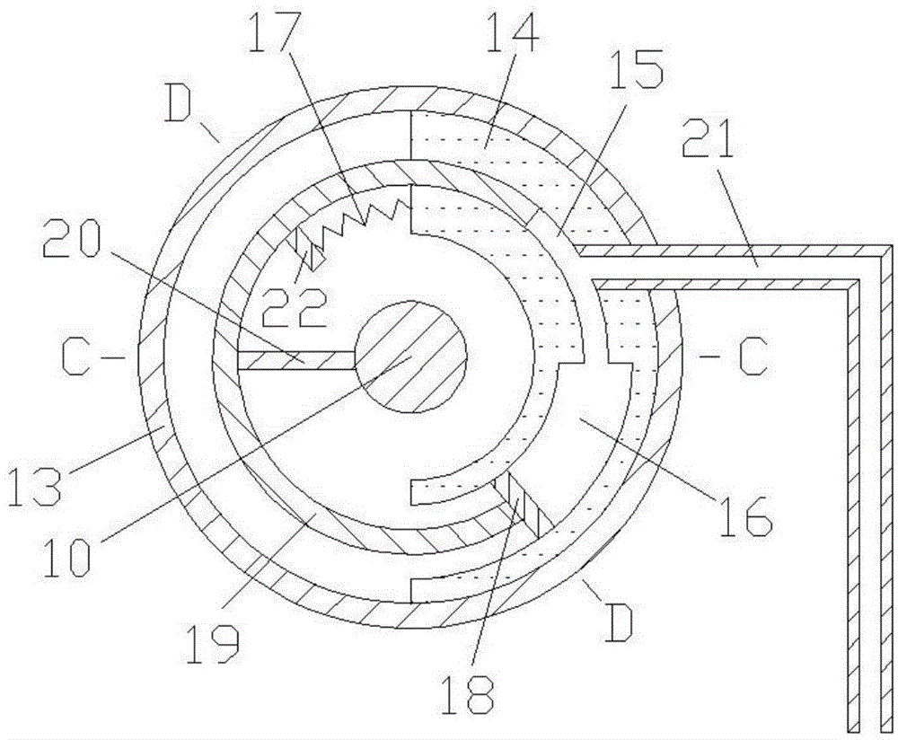
[0015] Examples of the present invention are Figure 1 to Figure 5 As shown, the present invention comprises an engine intake pipe 1, an air filter 2, a throttle valve 3, an engine 4, an engine exhaust pipe 5, a catalytic package 6, a muffler 7, a first connecting pipe 8, an adjustment cavity 9, a rotating shaft 10, Rotary plate 11, fixed plate 12, control cavity 13, fixed body 14, first inner tube 15, second inner tube 16, spring 17, partition plate 18, rotating body 19, connecting plate 20, second connecting tube 21, baffle Plate 22, the air outlet of the engine intake pipe 1 is connected with the air intake of the engine 4, the air outlet of the engine exhaust pipe 5 is connected with the exhaust passage of the engine 4, and the air filter 2 and the throttle valve 3 are arranged in sequence on the engine inlet. On the air pipe 1, the catalytic package 6 and the muffler 7 are sequentially arranged on the engine exhaust pipe 5, one end of the rotating shaft 10 is inlaid on th...


PUM


Abstract

The invention provides a continuous control mechanism and belongs to the technical field of internal combustion engines. The continuous control mechanism comprises an engine air inlet pipe, an engine, an engine exhaust pipe, connection pipes, internal pipes, an adjustment cavity, a control cavity and a rotation shaft. The adjusting cavity and the control cavity are coaxially connected through the rotation shaft. A baffle is fixedly connected with a rotation body. The left wall of a fixing body is connected with the baffle through a spring. One end of the second connection pipe penetrates through the fixing body to be communicated with the first internal pipe. The other end of the second connection pipe is communicated with the portion, located between a catalysis pack and a silencer, of the engine exhaust pipe. When the engine works at a low speed, the volume of the engine air inlet pipe is large, and when the engine works at a high speed, the volume of the engine air inlet pipe is small. The volume of the engine air inlet pipe can be self-adjusted. The continuous control mechanism is reasonable in design, simple in structure, and suitable for optimization design of naturally aspirated internal combustion engine air inlet systems.

Description

technical field [0001] The invention belongs to the technical field of internal combustion engines, and specifically relates to a continuous control mechanism capable of realizing the self-regulation of the volume of an intake pipe of a naturally aspirated engine. Background technique [0002] Present engines can be divided into naturally aspirated and supercharged, and supercharged can be divided into mechanical supercharging, turbocharging and the latest air wave supercharging. The naturally aspirated type does not have a supercharger, which means that the air simply passes through the air filter, throttle valve, and intake manifold to reach the cylinder, and gasoline is directly injected into the intake manifold through the fuel injector. Taking a four-cylinder engine as an example, a piston has four strokes for one work: down (the intake valve opens, there is a pressure difference, and the mixture of air and fuel enters the cylinder under the action of the pressure diffe...

Claims


Application Information

Patent Timeline
IPC IPC(8): F02B27/02
CPCY02T10/12
Inventor 储德新
Owner 储德新
Why Eureka
Try Eureka