Floating type draught fan mooring system, offshore wind generator unit and assembly method of offshore wind generator unit
A technology for wind turbines and mooring systems, which is applied to wind turbine components, wind engines, and wind power generation. It can solve problems such as poor wind and wave resistance, high overall center of gravity, and poor overall stability, and achieve improved wind and wave resistance. The effect of reducing safety hazards, preventing large-scale movement and even overturning
- Summary
- Abstract
- Description
- Claims
- Application Information
AI Technical Summary
Problems solved by technology
Method used
Image
Examples
Embodiment 1
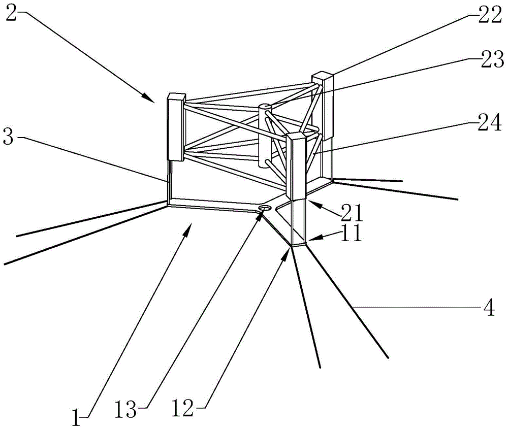
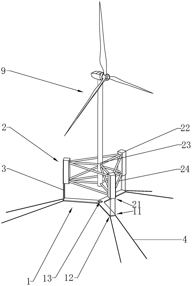
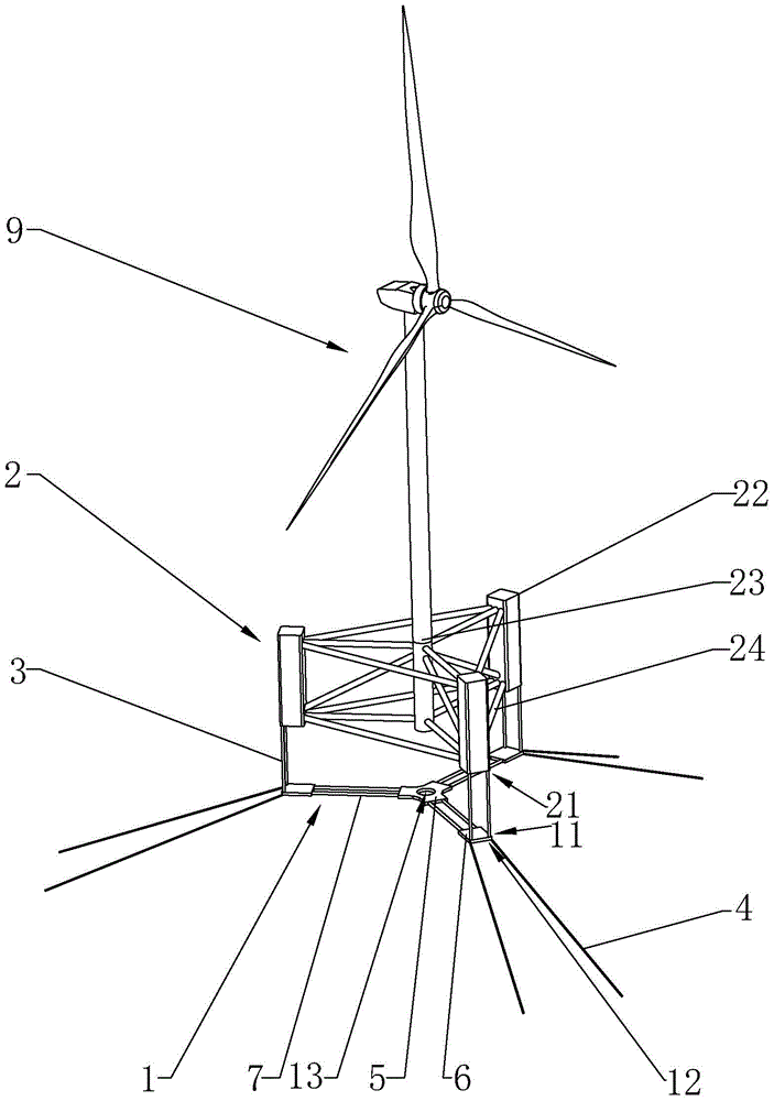
[0053] This embodiment mainly introduces the overall structure of the mooring system. Such as figure 1 and figure 2 as shown, figure 1 It is one of the structural diagrams of the mooring system of the embodiment of the present invention, figure 2 It is the second structural diagram of the mooring system of the embodiment of the present invention. in, figure 1 Only the overall structure of the mooring system is shown, figure 2 It shows the structure of the whole wind generating set including the wind generating set (hereinafter referred to as the fan 9 ) and the mooring system. The floating wind turbine mooring system of the embodiment of the present invention includes a rigid weight 1 and a floating foundation 2, the floating foundation 2 is provided with a plurality of first cable fixing parts 21, and the rigid weight 1 is provided with a plurality of second cables The fixing part 11 and the plurality of third cable fixing parts 12, the plurality of first cable fixin...
Embodiment 2
[0070] Since the system of the embodiment of the present invention belongs to the constrained mooring system, it has a significant restraint effect on the in-plane and out-of-plane motion of the floating fan 9. Therefore, the motion performance of the floating foundation 2 itself is not high, and the corresponding structural main The scale can be appropriately reduced, reducing the structural weight of the floating foundation 2 and reducing the structural cost.
[0071] Optionally, in order to set the first cable 3 into an adjustable structure, correspondingly, the first cable fixing part 21 may include a hoist, a cable pulley and a chain stopper (not shown in the figure) arranged on the floating foundation 2 ), the fairlead pulley can be arranged on the end column 22 (specifically, it can be arranged on the lower end or the side wall of the end column 22), the winch can be arranged on the end column 22, or can be arranged on the working platform of the floating foundation , t...
Embodiment 3
[0078] This embodiment mainly illustrates an optional structure of the rigid weight 1 . Such as figure 1 and figure 2 The rigid weight 1 can be set as a Y-shaped structure as a whole, and the three sides of the rigid weight have the same structure, and the angle between the three sides is 120 degrees. When the first cable 3 is tensioned and the floating foundation 2 and the rigid weight 1 is in a horizontal state, the center of the rigid weight 1 is located on the central axis of the floating foundation 2. Further, the above-mentioned Y-shaped structure has three sides with equal lengths extending in three directions, the second cable 4 fixed part is located at the end of the upper surface of the three sides of the Y-shaped rigid weight 1, and the third cable is fixed The portion 12 is located at the end of the lower surface of the three sides of the rigid weight 1 . In addition, the end points of the three sides of the Y-shaped rigid weight 1 can just correspond to the th...
PUM
 Abstract
Description
Claims
Application Information
 - R&D
- Intellectual Property
- Life Sciences
- Materials
- Tech Scout
- Unparalleled Data Quality
- Higher Quality Content
- 60% Fewer Hallucinations
Browse by: Latest US Patents, China's latest patents, Technical Efficacy Thesaurus, Application Domain, Technology Topic, Popular Technical Reports.
© 2025 PatSnap. All rights reserved.Legal|Privacy policy|Modern Slavery Act Transparency Statement|Sitemap|About US| Contact US: help@patsnap.com


