
Shadow Moire measuring system for automatic compensation of contrast of fringe pattern

An automatic compensation and measurement system technology, applied in the direction of measuring devices, instruments, optical devices, etc., can solve the problems of fringe contrast reduction in fringe patterns, affecting phase extraction and phase unwrapping, etc.

Inactive Publication Date: 2015-05-20
HUBEI UNIV OF AUTOMOTIVE TECH
View PDF5 Cites 7 Cited by
  • Summary
  • Abstract
  • Description
  • Claims
  • Application Information

AI Technical Summary

Problems solved by technology

[0003] In phase-shifted Shadow Moiré measurement, the fringe pattern information is processed by obtaining fringe patterns with different phases. In this process, since the measured object is far away from the grating to form a phase-shifted fringe pattern, the fringe contrast of the fringe pattern will gradually decrease, which will affect the Subsequent phase extraction and phase unpacking, so the automatic compensation of fringe contrast can improve the stability and measurement accuracy of the measurement, but relatively requires the measurement system

Method used

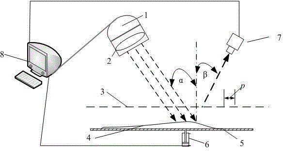
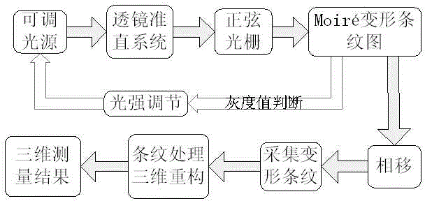
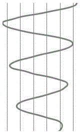

Image

  • Shadow Moire measuring system for automatic compensation of contrast of fringe pattern
  • Shadow Moire measuring system for automatic compensation of contrast of fringe pattern
  • Shadow Moire measuring system for automatic compensation of contrast of fringe pattern

Examples


Embodiment Construction

[0021] The present invention will be further described below in conjunction with accompanying drawing and example.

[0022] The fringe image contrast automatic compensation Shadow Moiré measurement system based on phase shift technology, including an adjustable light source 1 and a stage 5, the object 4 to be measured is arranged on the stage 5, and a sinusoidal grating 3 is arranged above the object 4 to be measured; The adjustable light source 1 projects parallel light through the lens collimation system 2 and illuminates the sinusoidal grating 3. The sinusoidal grating 3 overlaps the shadow grating modulated by the surface shape of the measured object 4 to form a moiré fringe pattern, and the generated moiré deformed fringe pattern passes through the CCD camera 7 The collected processing is transmitted to the control system 8 .

[0023] The sinusoidal grating 3 is parallel to the stage 5 .

[0024] The pitch of the sinusoidal grating 3 is P, wherein the pitch of P is 0.08 ...


PUM

PropertyMeasurementUnit
Pitchaaaaaaaaaa

Abstract

The invention relates to a Shadow Moire measuring system for automatic compensation of contrast of a fringe pattern. The measuring system is characterized in that a to-be-tested object is arranged on an object carrying table, and a sinusoidal grating is arranged above the to-be-tested object; an adjustable light source is used for projecting parallel light through a lens collimating system, the parallel light is irradiated to the sinusoidal grating which is parallel with the object carrying table, the sinusoidal grating is overlapped with a shadow grating which is modulated by the surface shape of the to-be-tested object to form a moire fringe pattern, and a generated moire deformation fringe pattern is collected, processed and transmitted by a CCD (charge coupled device) camera; the pitch of the sinusoidal grating is P, and P is 0.08mm or 0.1mm or 0.25mm; the adjustable light source is used for projecting the parallel light through the lens collimating system, the parallel light is irradiated to the sinusoidal grating and form an incident angle alpha with the sinusoidal grating, the CCD camera is used for collecting the moire fringe at an angle beta with the sinusoidal grating, and a servo motor is arranged under the object carrying table. The measuring system has the advantages that by obtaining the change rule of the gray level of any point on the fringe pattern, the change of fringe contrast of the fringe pattern is compensated by automatically adjusting the light intensity, so the fringe pattern is collected, and the basic uniform contrast is maintained; the measuring reliability and measuring accuracy are improved, and the measuring system is suitable for the surface non-contact three-dimensional optical measurement.

Description

technical field [0001] The invention relates to a Shadow Moiré measurement system, in particular to an automatic compensation Shadow Moiré measurement system for fringe image contrast based on phase shift technology. Background technique [0002] Shadow Moiré non-contact three-dimensional optical surface measurement technology uses light to project onto the grating to generate a shadow grating on the surface of the measured object, and the shadow grating will be deformed by the modulation of the surface shape of the measured object, and the shadow is observed from the CCD camera Grating overlaps grating to form moiré deformed fringes. The deformed fringe contains the surface information of the object, and the measured surface topography information is obtained by analyzing the deformed fringe, and the phase shift technology is used to improve the measurement accuracy. Shadow Moiré optical 3D measurement technology is widely used in computer vision, profiling of mechanical...

Claims


Application Information

Patent Timeline
IPC IPC(8): G01B11/25
Inventor 张伟任爱华曾国华孙国兴刘强王欢王红霞
Owner HUBEI UNIV OF AUTOMOTIVE TECH
Learn More