
A hydraulically loaded ball-on-disk type elastohydrodynamic friction tester

A hydraulic loading and friction technology, applied in instruments, measuring devices, mechanical devices, etc., can solve the problems of vibration of ball and disk specimens, inaccurate hydraulic loading, difficult processing, etc., to achieve safe and reliable operation, improve stability, The effect of preventing vibration

Active Publication Date: 2017-06-09
QILU UNIV OF TECH
View PDF5 Cites 0 Cited by
  • Summary
  • Abstract
  • Description
  • Claims
  • Application Information

AI Technical Summary

Problems solved by technology

For the test of point contact elastohydrodynamic lubrication friction, a four-disc machine is used to measure the disc test piece. The conical surface and the spherical surface contact are used, but such a spherical disc test piece is difficult to process, and the hydraulic loading is inaccurate, so it is rarely used.
Generally, the ball-on-disk type elastohydrodynamic friction tester is more commonly used. The ball-on-disk type elastohydrodynamic friction tester commonly has two structures: lever loading and hydraulic loading. Although the lever loading is accurate, but because it is rigid loading, it will cause The vibration of the ball-disk specimen in motion, and because of the weight loading, the continuous loading of the load cannot be realized
The fatal flaw of the hydraulic loading method given in the published literature is that the loading is unstable, and it is difficult to adjust the exact value of the required loading load, resulting in inaccurate loading and inaccurate measurement of the added load, which is Due to the defects in the mechanical structure design of the main engine of the testing machine and the unreasonable structural design of the hydraulic oil supply device

Method used


Image

  • A hydraulically loaded ball-on-disk type elastohydrodynamic friction tester
  • A hydraulically loaded ball-on-disk type elastohydrodynamic friction tester
  • A hydraulically loaded ball-on-disk type elastohydrodynamic friction tester

Examples


Embodiment Construction

[0023] The present invention will be further described in detail below in conjunction with the accompanying drawings and specific embodiments.

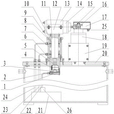
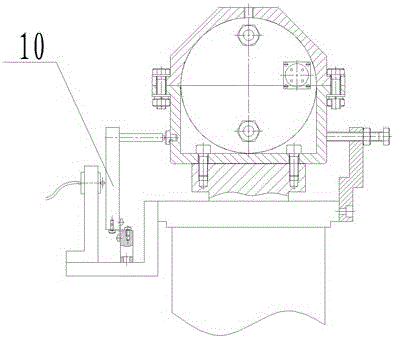
[0024] Such as figure 1 , a hydraulically loaded ball-on-disk type elastohydrodynamic friction tester of the present invention includes a box body 20, a hydrostatic shaft 11, a hydrostatic bearing 8, a hydrostatic bushing 7, an electric spindle A14, an electric spindle B18, a ball test piece 15, a disk Test piece 16, oil return pan 17, electric spindle A upper clamp seat 13, electric spindle A lower clamp seat 12, electric spindle B clamp seat 19, loading measurement system, friction measurement system 10.

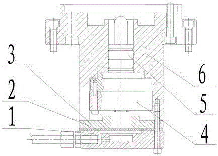
[0025] The loading measurement system includes a hydraulic station 21 , a loading oil pool 1 , a silicone pad 2 , a load sensor head cover 3 , a load sensor 4 , a loading body 5 , and a loading cover 6 . The load sensor 4 is fixedly connected with the loading body 5, the lower part of the load sensor 4 extends into the load senso...


PUM


Abstract

The invention discloses a hydraulic loading ball disc type elastic flow friction tester, which comprises a box body, a static-pressure shaft, a static-pressure bearing, a static-pressure shaft sleeve, an electric main shaft A, an electric main shaft B, a ball test piece, a disc test piece, an oil return disc, an electric main shaft A upper clamping seat, an electric main shaft A lower clamping seat, an electric main shaft B clamping seat, a loading measurement system, a friction measurement system and a hydraulic station. Hydraulic loading adopts a double-pump three-oil-way oil supply system, two ways of pressure oil are used for lubrication of the static-pressure bearing, and one way of pressure oil is used for a loading oil tank for hydraulic loading, and is provided with an automatic electro-hydraulic proportional valve. The electro-hydraulic proportional valve and a load sensor form a closed loop control circuit for guaranteeing the stability of oil pressure of the loaded oil way and the accuracy of load. The hydraulic loading ball disc type elastic flow friction tester is simple in structure, continuous loading can be conducted, the load loading is stable and the measurement precision is high.

Description

technical field [0001] The invention relates to the technical field of lubricating oil testing, in particular to a hydraulically loaded ball-on-disk type elastohydrodynamic friction tester. Background technique [0002] The EHL friction state is a common and important friction state in industrial production. Most commonly used mechanical parts such as gears, bearings and cams work in this friction state. The elastohydrodynamic friction of the lubricant has a great influence on the motion state and dynamic characteristics of the rolling elements in the bearing and the driven gear in the gear pair, thus affecting the life of the bearing and the gear. The use range and friction characteristics of different lubricants are very different. In order to give correct suggestions on the use of lubricants in engineering applications, the current theoretical calculations cannot meet the accuracy required by engineering, and the lubrication is generally obtained through experiments. The...

Claims


Application Information

Patent Timeline
Patent Type & Authority Patents(China)
IPC IPC(8): G01N19/02
Inventor 王燕霜李璞曹佳伟承军伟李刚
Owner QILU UNIV OF TECH
Learn More