Positive electrode grid line of solar cell, solar cell and manufacturing method of solar cell

A technology of solar cells and manufacturing methods, applied in the direction of final product manufacturing, sustainable manufacturing/processing, circuits, etc., can solve the problems of affecting current collection, increasing the risk of disconnection, and affecting battery quality, so as to improve conversion efficiency, Conducive to pooling and cost-increasing effects

Inactive Publication Date: 2015-05-20
CHINA SUNERGY CO LTD
View PDF4 Cites 10 Cited by
  • Summary
  • Abstract
  • Description
  • Claims
  • Application Information

AI Technical Summary

Problems solved by technology

However, reducing the sub-grid width will be restricted by screen specifications, printing conditions, environmental factors, paste characteristics and other conditions, increasing the risk of disconnection, especially with the assistance of electroluminescence (EL) detection equipment, This is particularly the case
Broken wires not only affect the collection of current, but also affect the quality of the battery at the component end

Method used


Image

  • Positive electrode grid line of solar cell, solar cell and manufacturing method of solar cell
  • Positive electrode grid line of solar cell, solar cell and manufacturing method of solar cell
  • Positive electrode grid line of solar cell, solar cell and manufacturing method of solar cell

Examples


Embodiment 1

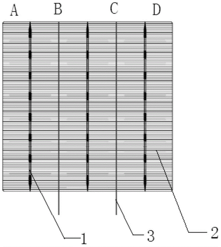
[0027] Embodiment 1: This implementation provides a solar cell positive electrode grid line, including at least 3 main grid lines 1 and a plurality of auxiliary grid lines 2, and the grid line distribution schematic diagram is as follows figure 1 As shown, there are 3 main grid lines, which divide the cell into four areas A, B, C, and D.

[0028] The three main gate lines 1 are arranged parallel to each other, and the auxiliary gate lines 2 are arranged parallel to each other and perpendicular to the main gate lines 1 . The central axis between two adjacent main grid lines 1 is the main grid center line 3, and the width of the auxiliary grid line 2 is from the main grid line 1 to the main grid center line 3 or the positive electrode of the battery The margins are distributed in a stepwise reduction.

[0029] The schematic diagram of the sub-grid width distribution is shown in figure 2 As shown, in the regions B and C, the width of the auxiliary gate line 2 is distributed in...

Embodiment 2

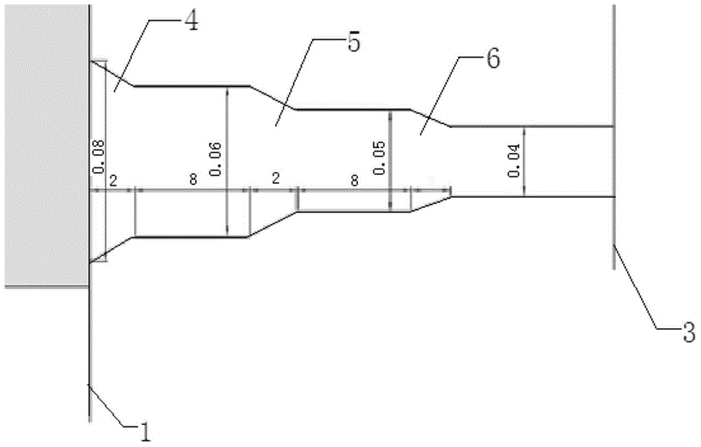
[0034] Embodiment 2: This implementation provides a positive electrode grid wire of a solar cell, and the structural diagram is as follows image 3 As shown, its structure is basically the same as that of Embodiment 1, the difference is that the width of the sub-grid line 2 is reduced in a stepped manner, and its starting position is the connection between the sub-grid line and the main grid line. The width of the starting position is 80 μm, the width of the ending position is 40 μm, and the waistline height of the step is 1 mm. .

[0035] For this embodiment 2 image 3 The positive electrode grid line of the structure was tested, and the test conditions and results are as follows:

[0036] The test items are as follows:

[0037] Test 10,000 cells on two production lines with the same configuration using the newly designed pattern and the original design pattern.

[0038] Every 1 hour, take 24 finished cells for EL test.

[0039] Count the number of EL broken grids, calcu...

Embodiment 3

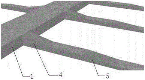
[0043]Embodiment 3: This implementation provides a positive electrode grid line of a solar cell, the structure of which is basically the same as that of Embodiment 1, the difference is that the height of the auxiliary grid line is from the main grid line to the center of the main grid Lines or the edge of the positive electrode of the battery are in a stepwise decreasing distribution, and the width distribution step of the auxiliary grid line corresponds to the height distribution step of the auxiliary grid line, and the height of the auxiliary grid line is in a stepwise decreasing distribution. Such as Figure 4 shown.

[0044] In the embodiment, the width of the sub-grid line 2 is reduced in a three-step manner. Therefore, in this embodiment, the height of the sub-grid line 2 is distributed in a three-step manner. 1 equal height, the height is 25 μm, and the height of the end position is 22 μm; the start position of the second step 5 is equal to the end position of the firs...


PUM


Abstract

The invention discloses a positive electrode grid line of a solar cell, comprising at least three main grid lines and a plurality of auxiliary grid lines; the main grid lines are arranged in a mutual parallel manner; the auxiliary grid lines are parallel to each other and perpendicular to the main grid lines; every two adjacent central axial lines between the two main grid lines are main grid central lines; the widths of the auxiliary grid lines are distributed in a stepped reduction manner from the main grid lines to the main grid central lines or edges of a positive electrode of the cell. According to the positive electrode grid line of the solar cell, the solar cell and the manufacturing method of the solar cell, the broken lines due to jump cut problem are avoided and the problem of EL (electroluminescence) broken lines is solved; meanwhile, the light interception area of the cell can further be increased, the current conduction capability is enhanced and the conversion efficiency of the cell is improved.

Description

technical field [0001] The present invention relates to a positive electrode grid wire of a solar cell, a solar cell and a manufacturing method thereof. More specifically, the present invention relates to a positive electrode grid wire of a solar cell, a solar cell and a manufacturing method thereof, which reduce the risk of disconnection. Background technique [0002] A crystalline silicon solar cell is a device that converts light energy into electrical energy by using the photovoltaic effect. Its positive electrode is divided into two parts, the main grid line and the sub-grid line. The main grid line is used for welding the solder strips at the component end And the derivation of electric current; The auxiliary gate line is used to collect electrons generated by the photovoltaic effect. As we all know, the solar cell electrodes have a great influence on the performance of the cell, and the factors that affect the performance of the front grid line mainly include ohmic co...

Claims


Application Information

Patent Timeline
Patent Type & Authority Applications(China)
IPC IPC(8): H01L31/0224H01L31/18
CPCH01L31/022425H01L31/022433H01L31/18Y02E10/50Y02P70/50
Inventor 杨喜平梅晓东杜欢
Owner CHINA SUNERGY CO LTD
Why Eureka
Try Eureka