
Temperature control heat dissipation power-saving cabinet

A technology of power-saving cabinets and temperature control devices, which is applied in the cooling/ventilation of substations/switchgears, etc., which can solve the problems of reduced life of electrical components, affect the safe operation of equipment, and affect service life, etc., and achieve the effect of prolonging life

Inactive Publication Date: 2015-05-20
STATE GRID CORP OF CHINA +2
View PDF6 Cites 12 Cited by
  • Summary
  • Abstract
  • Description
  • Claims
  • Application Information

AI Technical Summary

Problems solved by technology

Electrical components work under high temperature conditions for a long time, which will affect their service life
At present, in the electrical industry, there is no fresh air system for the feeder cabinet of the power-saving cabinet. Generally, the cabinet body is closed. Since the feeder cabinet of the switch cabinet does not have a fresh air system, the accumulated heat in the cabinet will cause the temperature to continue to rise. If the temperature is too high, all the electrical components in the drawer of the power saving cabinet will work at a high temperature, resulting in electrical The life of the components is reduced, which will affect the safe operation of the equipment

Method used


Image

  • Temperature control heat dissipation power-saving cabinet
  • Temperature control heat dissipation power-saving cabinet

Examples


Embodiment Construction

[0013] The technical solution of this patent will be further described in detail below in conjunction with specific embodiments.

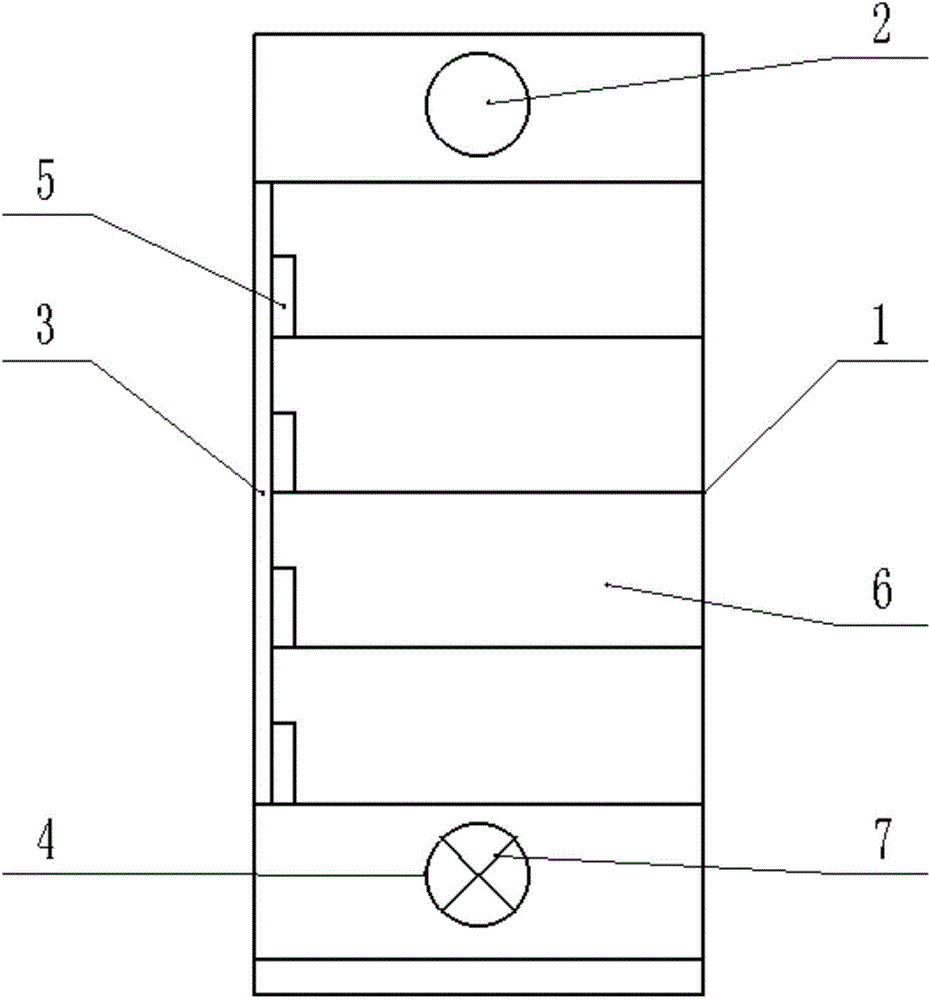
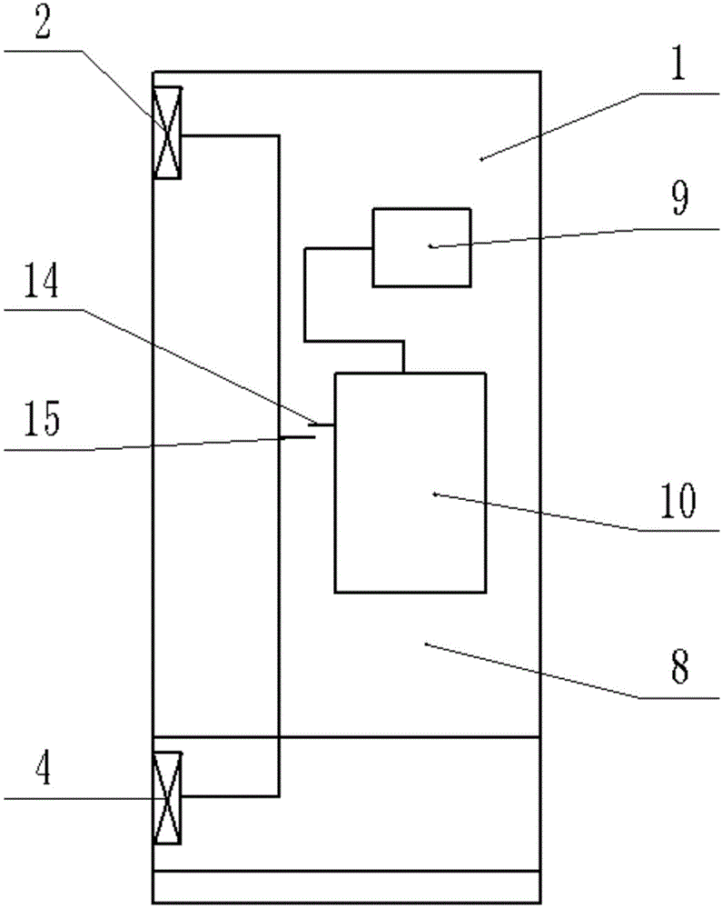
[0014] see Figure 1-2 , a temperature-controlled heat dissipation and power-saving cabinet, comprising a cabinet body 1, an air duct 3 and a temperature control device 8, the cabinet body 1 is provided with a ventilation device, and the ventilation device includes an exhaust fan 2 and an air duct 3, the The uppermost part of the front of the cabinet body 1 is provided with an exhaust fan 2; the side of the cabinet body 1 is provided with an air duct 3, the air duct 3 is arranged up and down along the cabinet body 1, and the air duct 3 is provided with an air inlet 4 at the bottom. Suction fans 7 are installed at the air inlet 4, and some branch pipes 5 are arranged on the air duct 3 to connect the drawers 6 of each power-saving cabinet; Electric current will inevitably generate a large amount of heat, so when the exhaust fan 2 is installed on the...


PUM


Abstract

The invention discloses a temperature control heat dissipation power-saving cabinet which comprises a cabinet body, an air duct and a temperature control device. The cabinet body is provided with a ventilation device; the ventilation device comprises an exhaust fan and the air duct; the exhaust fan is formed at the topmost part of the front side of the cabinet body; the air duct is formed at the side of the cabinet body; the air duct is formed vertically along the cabinet body; an air inlet is formed in the bottom of the air duct; an air draft fan is mounted at the air inlet; a plurality of branch pipes are arranged on the air duct and are connected with corresponding drawers of the power-saving cabinet; the temperature control device comprises an active contact and a passive contact; the active contact is positioned above the passive contact and is not in contact with the passive contact; the active contact is made of a bimetallic strip. According to the temperature control heat dissipation power-saving cabinet, the temperature-controlled fans are utilized to cool electrical appliance elements; working temperatures of the electrical appliance elements are reduced; the service lives are prolonged; the temperature-controlled fans can only be started when the temperature reaches a certain value, so that the fans are prevented from being worn due to long-term start.

Description

technical field [0001] The invention relates to a relatively large range, in particular to a temperature-controlled heat dissipation and power-saving cabinet. Background technique [0002] Power saving cabinet, also called control cabinet, is also a kind of power saving device, which is suitable for industrial, commercial and other large power consumption places. The power-saving cabinet improves the relevant electrical parameters through its own electrical characteristics in the circuit, thereby producing a power-saving effect. The power-saving cabinet is generally relatively large in size, and there are many electrical components installed inside, and its heat generation is very large, especially transformer. Electrical components work under high temperature conditions for a long time, which will affect their service life. At present, in the electrical industry, there is no fresh air system for the feeder cabinet of the power-saving cabinet. Generally, the cabinet body i...

Claims


Application Information

Patent Timeline
Patent Type & Authority Applications(China)
IPC IPC(8): H02B1/56
CPCH02B1/56
Inventor 许浩李念淼陈颖朱晞旸王海军卢轶人
Owner STATE GRID CORP OF CHINA
Learn More