
Improved motor

An improved shell technology, applied in the direction of electrical components, electromechanical devices, electric components, etc., can solve the problems of loose motor structure, increased energy consumption, waste, etc., to increase integrity and connection strength, reasonable shell design, and ensure normal operation The effect of operation

Inactive Publication Date: 2015-05-20
宁波金锐机械有限公司
View PDF5 Cites 0 Cited by
  • Summary
  • Abstract
  • Description
  • Claims
  • Application Information

AI Technical Summary

Problems solved by technology

[0003] In the existing motors, the connection method between the carbon brush assembly and the motor casing is usually to directly connect the carbon brush holder of the carbon brush assembly to the outer surface of the motor casing through a fixing piece. This connection method is simple, but at the same time causes the carbon brush assembly The problem of unstable connection with the motor casing, therefore, people improve the motor casing, and another connection method appears, which is to increase the volume of the motor casing so that it can accommodate the carbon brush assembly, so as to increase the carbon brush assembly The connection stability with the motor casing, however, due to the increase in the volume of the motor casing, the input of materials and production costs, resulting in a certain degree of waste, and at the same time, the structure of the motor is loose, increasing its energy consumption. In addition, in the existing motor, the outer surface of the rotating shaft is smooth, and the rotor core and the commutator are installed on the rotating shaft and rotate together with the rotating shaft. Under the resistance of the rotor core and the commutator, the rotor core and the commutator The commutator tends to rotate relative to the rotating shaft, which is the so-called "slip", especially the commutator, which is in contact with the carbon brush assembly. When the "slip phenomenon occurs," the carbon brush assembly cannot move on the surface of the commutator. cause the entire motor to fail to operate normally

Method used


Image

  • Improved motor
  • Improved motor
  • Improved motor

Examples


Embodiment Construction

[0027] The following are specific embodiments of the present invention and in conjunction with the accompanying drawings, the technical solutions of the present invention are further described, but the present invention is not limited to these embodiments.

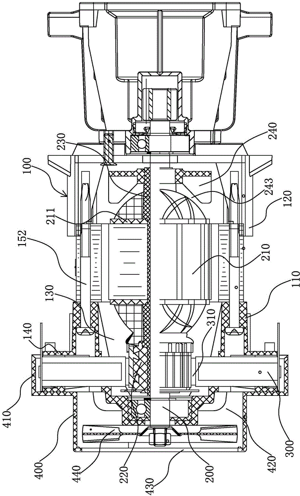
[0028] Such as figure 1 As shown, an improved motor of the present invention includes a casing 100, the casing 100 includes an upper casing 110 and a lower casing 120 fixedly connected with the upper casing 110, and a There is a receiving cavity 130 .

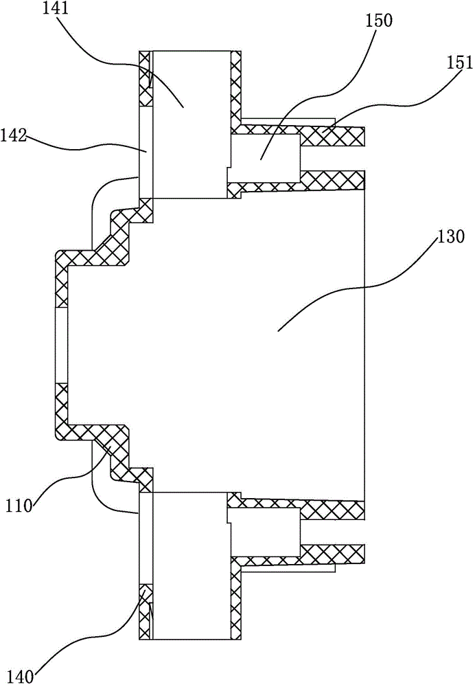
[0029] Such as figure 1 , figure 2 As shown, two carbon brush mounting parts 140 integrally formed with the upper housing 110 are arranged laterally on the outer surface of the upper housing 110. The carbon brush mounting parts 140 are arranged symmetrically and on the same straight line. Each carbon brush An installation channel 141 is opened on the installation part 140 , and two ends of the installation channel 141 communicate with the accommodating chamber 130 and t...


PUM


Abstract

The invention provides an improved motor, belongs to the technical field of motors, and aims to solve the technical problems of instable connection of an existing carbon brush component and the motor and poor synchronization effect of a reverser and a rotating shaft. The improved motor comprises a shell, a rotor component and the carbon brush component, wherein the rotor component comprises the rotating shaft, a rotor core and the reverser; the two ends of the rotating shaft penetrate through the shell respectively and are connected with the shell; the shell is provided with a carbon brush mounting part; the carbon brush mounting part is provided with a mounting passage which is communicated with the interior of the shell, is positioned in the mounting passage and is in contact with the reverser; one end of the shell is also provided with an end cover for pressing the rear end of the carbon brush component in a covering manner; an insulating sleeve sleeves the rotating shaft; the rotor core and the reverser are both arranged on the insulating sleeve; the carbon brush mounting part and the shell are integrally formed, so the integrity and the connection strength of the carbon brush mounting part and the shell are increased; the outer surface of the rotating shaft is provided with the insulating sleeve, so relative rotation of the rotor core, the reverser and the rotating shaft does not occur easily.

Description

technical field [0001] The invention belongs to the technical field of motors and relates to an improved motor. Background technique [0002] Motor refers to an electromagnetic device that realizes the conversion or transmission of electric energy according to the law of electromagnetic induction. During the process of converting electric energy into kinetic energy, the winding group is easy to generate heat, which affects the conversion rate of energy. [0003] In the existing motors, the connection method between the carbon brush assembly and the motor casing is usually to directly connect the carbon brush holder of the carbon brush assembly to the outer surface of the motor casing through a fixing piece. This connection method is simple, but at the same time causes the carbon brush assembly The problem of unstable connection with the motor casing, therefore, people improve the motor casing, and another connection method appears, which is to increase the volume of the moto...

Claims


Application Information

Patent Timeline
Patent Type & Authority Applications(China)
IPC IPC(8): H02K5/14
CPCH02K5/145H02K13/006
Inventor 吴雷幸徐银林
Owner 宁波金锐机械有限公司
Features
  • Generate Ideas
  • Intellectual Property
  • Life Sciences
  • Materials
  • Tech Scout
  • Unparalleled Data Quality
  • Higher Quality Content
  • 60% Fewer Hallucinations
Learn More