
Automatic machining equipment for three-way pipe

A technology for processing equipment and three-way pipes, applied in metal processing equipment, heat exchange equipment, manufacturing tools, etc., can solve problems such as endangering worker safety, low production efficiency, and being unsuitable for mass production, so as to achieve mass production and production efficiency. high effect

Active Publication Date: 2015-05-27
浙江长兴和良智能装备有限公司
View PDF7 Cites 35 Cited by
  • Summary
  • Abstract
  • Description
  • Claims
  • Application Information

AI Technical Summary

Problems solved by technology

The processing of traditional three-way pipes, one is manual, and the other is semi-automatic processing. Among them, the manual method uses pure manual flaring and flat forming, which is time-consuming, labor-intensive, low in production efficiency, and high in labor costs. It is not suitable for mass production.
The semi-automatic processing method adopts semi-mechanical and semi-manual operation. The worker first clamps the tee on the machine tool through the fixture, and then expands the mouth with the flaring tool. After the flaring is completed, the workpiece is manually disassembled; the worker then clamps the tee through the fixture. On the machine tool, the workpiece is flattened and formed by the flattening device. After the flattening and forming, the workpiece is manually disassembled to complete the processing of the tee. The production efficiency of this semi-automatic processing method is higher than that of the manual method. However, due to manual feeding And clamping and then flaring, and manual unloading and clamping before flattening and forming, the manual operation time is long, so the processing efficiency is still not high, the labor cost is high, and it is not suitable for mass production, and there are still problems due to human misoperation, etc. endanger worker safety

Method used


Image

  • Automatic machining equipment for three-way pipe
  • Automatic machining equipment for three-way pipe
  • Automatic machining equipment for three-way pipe

Examples


Embodiment Construction

[0030] In order to make the purpose, technical solutions and advantages of the embodiments of the present invention more clear, the following will clearly and completely describe the technical solutions of the embodiments of the present invention in conjunction with the drawings of the embodiments of the present invention. Apparently, the described embodiments are some, not all, embodiments of the present invention. Based on the described embodiments of the present invention, all other embodiments obtained by persons of ordinary skill in the art without creative efforts shall fall within the protection scope of the present invention.

[0031] In describing the present invention, it should be understood that the terms "center", "longitudinal", "transverse", "length", "width", "thickness", "upper", "lower", "front", " Orientation or position indicated by "back", "left", "right", "vertical", "horizontal", "top", "bottom", "inner", "outer", "clockwise", "counterclockwise", etc. T...


PUM


Abstract

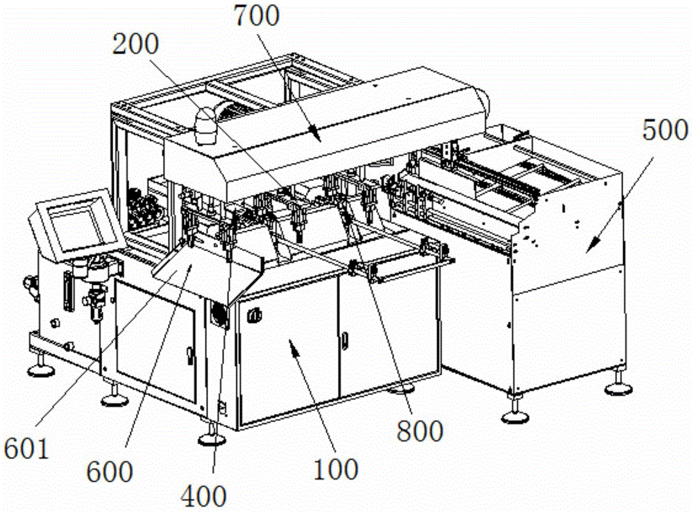
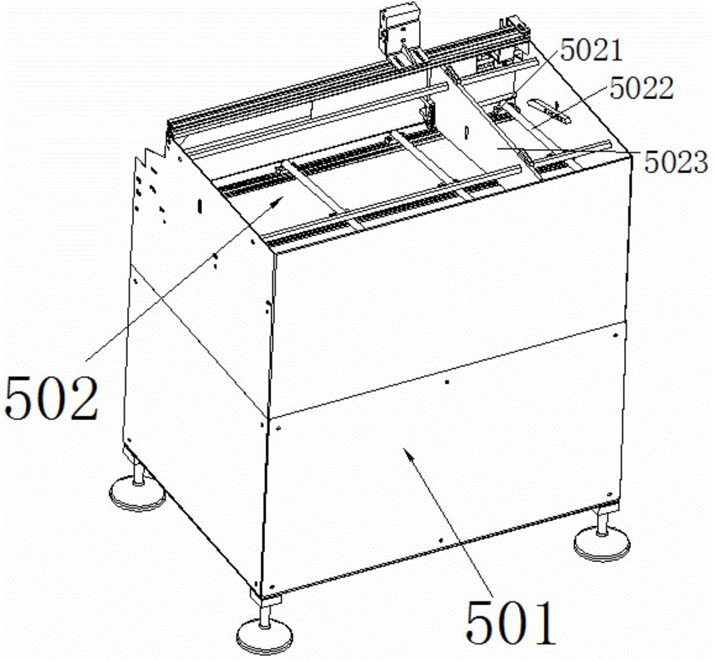
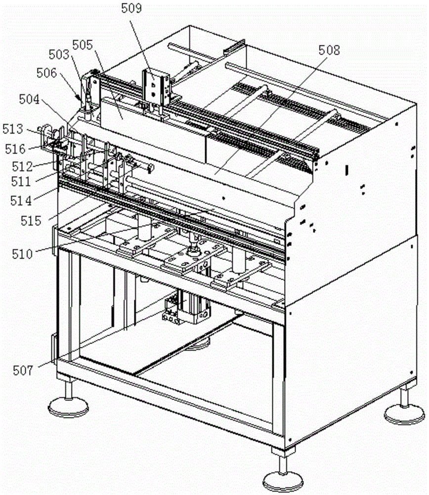
The invention discloses automatic machining equipment for a three-way pipe. The invention discloses a machine frame, a flaring mechanism and a flattening forming mechanism which are arranged on the machine frame, a feeding device which is arranged at a feeding opening, a discharging device which is arranged at a discharging opening, and a manipulator mechanism which is arranged above the flaring mechanism and the flattening forming mechanism; the manipulator mechanism conveys a workpiece to the flaring mechanism from the feeding opening of the feeding device for the flaring mechanism to perform flaring on the workpiece, and conveys the workpiece to the flattening forming mechanism from the flaring mechanism for the flattening forming mechanism to form the workpiece; the formed workpiece is discharged by put into the discharging device through the manipulator mechanism. The invention provides the automatic machining equipment for the three-way pipe, the automatic machining of the flaring and the flattening forming of the three-way pipe is realized; the production efficiency is high; the automatic machining equipment is suitable for batch production.

Description

technical field [0001] The invention relates to the processing of three-way pipes, in particular to an automatic processing equipment for three-way pipes. Background technique [0002] Tee pipes are commonly used to connect multi-channel pipe fittings in air-conditioning and refrigeration systems. The processing of the three-way pipe generally needs to be flared at one end first, and then flattened at the end after the flare. The processing of traditional three-way pipes, one is manual, and the other is semi-automatic processing. Among them, the manual method uses pure manual flaring and flat forming, which is time-consuming, labor-intensive, low in production efficiency, and high in labor costs. It is not suitable for mass production. . The semi-automatic processing method adopts semi-mechanical and semi-manual operation. The worker first clamps the tee on the machine tool through the fixture, and then expands the mouth with the flaring tool. After the flaring is complete...

Claims


Application Information

Patent Timeline
Patent Type & Authority Applications(China)
IPC IPC(8): B21D53/02B21D41/02B21D31/06B21D43/02B21D43/10B21D45/06
CPCB21D31/06B21D41/02B21D43/003B21D43/105B21D45/06B21D53/06
Inventor 沈杰张良
Owner 浙江长兴和良智能装备有限公司
Learn More