Building composite foundation pile top pre-piercing mattress layer

A technology of composite foundation and mattress, which is applied in construction, infrastructure engineering, infrastructure testing and other directions, can solve problems such as unreasonable, lagging bearing effect, poor economy, etc., and achieves simple calculation method and strong engineering. Practicality and the effect of reasonably adjusting stiffness

Active Publication Date: 2015-05-27
JIANGSU PROVINCIAL ARCHITECTURAL D&R INST
View PDF6 Cites 4 Cited by
  • Summary
  • Abstract
  • Description
  • Claims
  • Application Information

AI Technical Summary

Problems solved by technology

[0007] By changing the thickness of the pile top cushion, although it can adjust the pile-soil stress ratio and the pile and soil load, this adjustment effect also has limitations: on the one hand, when the soil quality is poor, generally a thinner cushion layer, in order to achieve a higher load sharing ratio of piles and ensure that the bearing function of the pile is fully exerted, but the cushion layer is too thin, the bearing effect of the soil can hardly be exerted, the economy is not good, and the cushion layer is difficult to achieve the weak reinforcement of the shallow layer The purpose of the soil is unreasonable; on the other hand, when the soil quality is good, in order to give full play to the bearing function of the soil, a thicker cushion is generally set.
However, the thicker cushion makes the load-bearing function of the pile lag behind. In order to realize the deformation coordination between the pile and the soil, the pile top needs to produce a large upward penetration. at the expense of settlement, therefore, this pile top penetration reduces the overall settlement of the increased composite foundation

Method used


Image

  • Building composite foundation pile top pre-piercing mattress layer
  • Building composite foundation pile top pre-piercing mattress layer
  • Building composite foundation pile top pre-piercing mattress layer

Examples


Embodiment Construction

[0041] Attached below Figure 1 to Figure 5 And the specific embodiment will further describe the pile top pre-piercing cushion layer of the building composite foundation of the present invention.

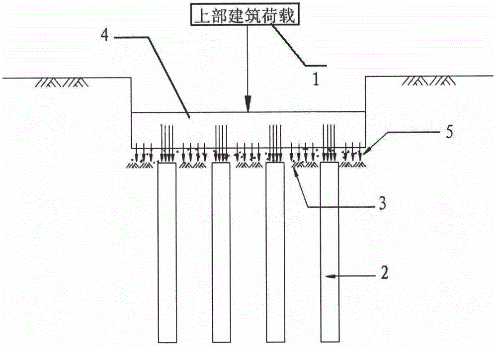
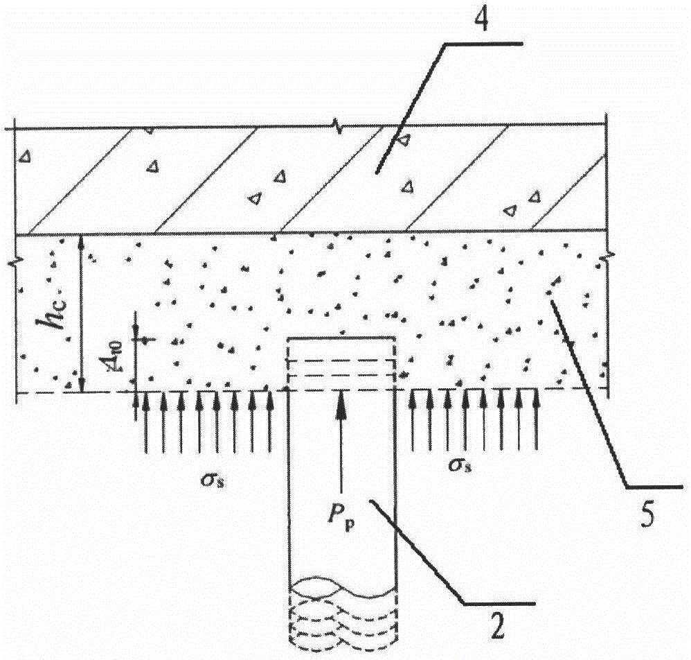
[0042] The invention discloses a pile top pre-piercing cushion layer of a building composite foundation, which comprises a cushion layer body 6 covering between the bottom surface of the foundation 4 and the top of a pile body 2, and the cushion layer body The bottom of 6 is provided with pre-piercing hole 61, and the size of pre-piercing hole 61 is used to coincide with the top of pile body 2.

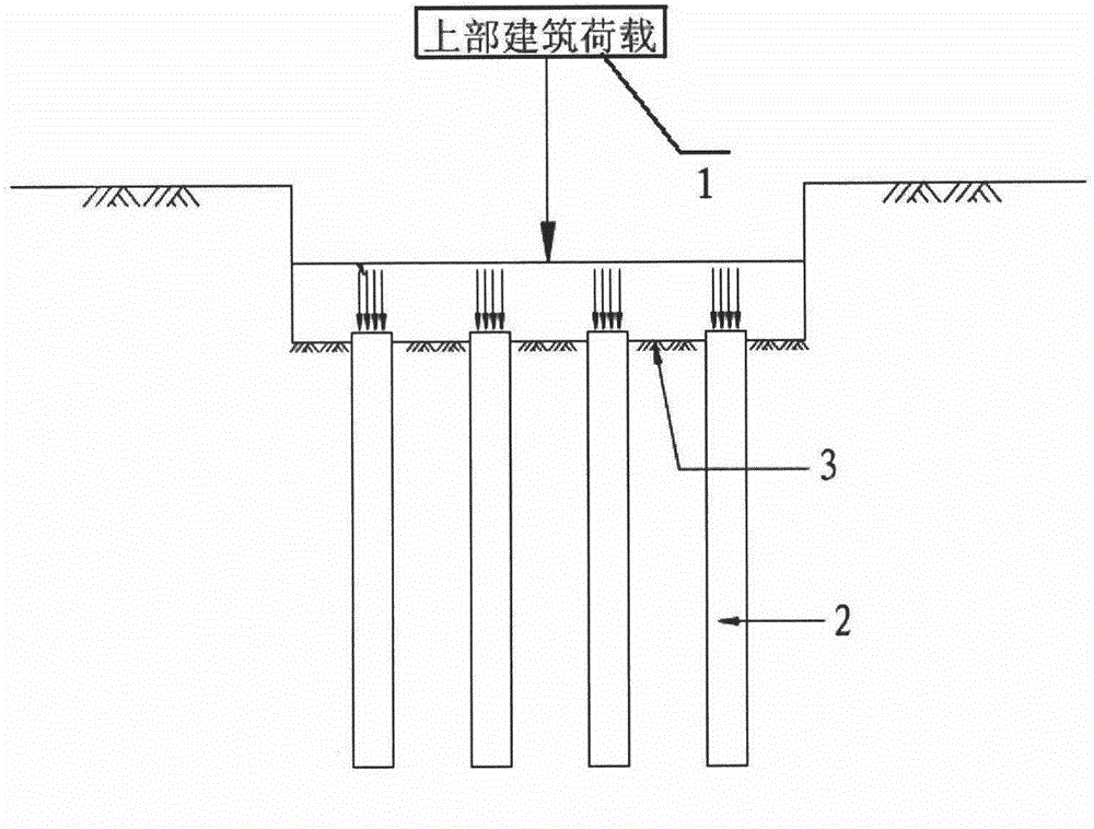
[0043] Such as figure 1 and figure 2 As shown, the conventional pile top cushion method of composite foundation is mostly "flush", that is, the top of the pile body and the top cushion of the soil between the piles can only have the same thickness. In the pre-piercing type cushion layer of the present invention, the depth of the pre-piercing hole 61 can be flexibly adjusted according t...


PUM


Abstract

The invention discloses a building composite foundation pile top pre-piercing mattress layer, which comprises a mattress layer body, wherein the mattress layer body covers a position between the bottom surface of a foundation and the top of a pile body, a pre-piercing hole is formed in the bottom of the mattress layer body, the size of the pre-piercing hole is anastomotic with the top of the pile body. Meanwhile, the invention discloses a calculation mode of the pre-piercing hole. The building composite foundation pile top pre-pierce mattress layer has the beneficial effects that the composite foundation conventional pile top pad layer methods most adopt flat type, i.e., the thickness of the pile top and between-pile soil top surface pad layers can only be identical, according to the pre-piercing mattress layer provided by the invention, the depth of the pre-piercing hole can be flexibly regulated according to the load size, soil property conditions and pad layer material properties of concrete engineering in accordance with the pile soil stress ratio requirement required to be reached in the design, different pad layer thickness and pre-piercing depth can be adopted in a combined way in different positions of the same building, the composite foundation rigidity can be reasonably regulated through the difference control on the depth of the pre-piercing hole, and the difference sedimentation of the foundation is reduced.

Description

technical field [0001] The invention relates to the field of construction, in particular to a pre-piercing cushion layer for pile tops of building composite foundations. Background technique [0002] Composite foundation, natural foundation and pile foundation are the three foundation forms commonly used in construction engineering. The essence of the composite foundation is to set piles (also known as reinforcements) in the foundation soil, so that the piles and the soil between the piles jointly bear the load of the superstructure. [0003] The composite foundation is composed of piles and soil. The material strength and stiffness of piles and soil are very different. Under the action of equal load, the deformation of piles is much smaller than that of the soil between piles. Such as figure 1 As shown, if the pile body is directly placed on the bottom of the foundation, under the action of the superstructure load 1, most of the superstructure load 1 will be transferred t...

Claims


Application Information

Patent Timeline
IPC IPC(8): E02D27/12E02D33/00
Inventor 陶景晖
Owner JIANGSU PROVINCIAL ARCHITECTURAL D&R INST
Why Eureka
Try Eureka