Automatic speed changer electric hydraulic cooling lubrication system and control system thereof

An automatic transmission, cooling and lubrication technology, applied in the direction of gear lubrication/cooling, transmission parts, belts/chains/gears, etc., can solve the problems of high cost and large space

Active Publication Date: 2019-09-10
CHINA FIRST AUTOMOBILE
View PDF24 Cites 12 Cited by
  • Summary
  • Abstract
  • Description
  • Claims
  • Application Information

AI Technical Summary

Problems solved by technology

However, the current on-demand active lubrication and cooling method needs to install pressure and flow sensors in the cooling and lubrication system. The control process needs to obtain real-time system pressure and flow signals through pressure and flow sensors to complete, which takes up a lot of space and costs high

Method used


Image

  • Automatic speed changer electric hydraulic cooling lubrication system and control system thereof
  • Automatic speed changer electric hydraulic cooling lubrication system and control system thereof
  • Automatic speed changer electric hydraulic cooling lubrication system and control system thereof

Examples


Embodiment 1

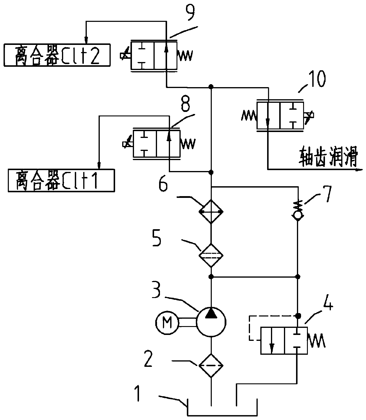
[0057] This embodiment is used in a dual-clutch automatic transmission with two lubricating oil channels independent of each other and a wet clutch, in which the shaft-tooth flow regulating device adopts the lubrication and cooling system of the shaft-tooth proportional flow control valve.

[0058] Such as figure 1 As shown, the electro-hydraulic cooling and lubricating system of the automatic transmission of the present invention includes: oil storage tank 1, oil suction filter 2, electro-hydraulic pump 3, unloading valve 4, electro-hydraulic pump outlet filter 5, cooler 6, one-way Valve 7, a first proportional flow control valve 8, a second proportional flow control valve 9 and a shaft tooth flow regulating device 10; wherein, the oil inlet of the oil suction filter 2 is connected to the oil storage tank 1, and the oil suction filter 2 The oil outlet of the electric hydraulic pump 3 is connected to the oil suction port of the electric hydraulic pump 3, and the oil outlet of ...

Embodiment 2

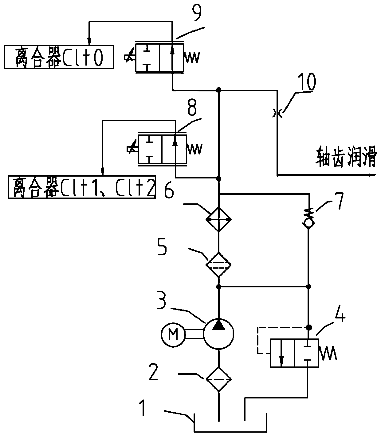
[0089] The difference between this embodiment and Embodiment 1 is that this embodiment is used for the automatic transmission lubrication system of hybrid vehicles, and the system includes three clutches, wherein clutch Clt0 is a separation clutch and has an independent lubricating oil passage; clutches Clt1, Clt2 The lubricating oil passages of the first proportional flow control valve 8 are connected in series with the lubricating oil passages of the clutches Clt1 and Clt2 to control the cooling and lubricating flow of the clutches Clt1 and Clt2; the oil outlet end of the second proportional flow control valve 9 Connect the lubricating oil channel of clutch Clt0 to control the cooling and lubricating flow of clutch Clt0. The shaft tooth flow regulating device 10 adopts a throttling hole; the diameter of the throttling hole is determined according to the lubrication flow requirement and the test calibration; in this embodiment, the diameter of the throttling hole can be set to...


PUM


Abstract

The invention relates to an automatic speed changer electric hydraulic cooling lubrication system. An oil inlet of an oil absorbing filter of the system is connected with an oil storage tank, and an oil outlet of the oil absorbing filter is connected with an oil suction port of an electric hydraulic pump. An oil outlet of the electric hydraulic pump is connected with an electric hydraulic pump outlet filter and an oil port in one end of an loading valve in parallel, the other end of the electric hydraulic pump outlet filter is connected with the inlet end of a cooler, and the outlet end of thecooler is connected with a plurality of clutch proportion flow control valves and the inlet end of a shaft tooth flow adjusting device in parallel; an oil port in the other end of the unloading valveis connected with the oil storage tank, and a one-way valve is connected to the outlet of the electric hydraulic pump and the outlet end of the cooler in parallel; the other ends of the clutch proportion flow control valves are connected with clutches; and the other end of the shaft tooth flow adjusting device is led to a shaft tooth cooling lubricating oil spraying pipe. The automatic speed changer electric hydraulic cooling lubrication system does not contain pressure and flow sensors, the control process can be finished without obtaining real-time system pressure and flow signals, and theoccupied space and cost of the system can be saved.

Description

technical field [0001] The invention belongs to the technical field of transmissions, and in particular relates to an electro-hydraulic cooling and lubricating system of a wet clutch automatic transmission and a control system thereof. Background technique [0002] During the operation of the car, the gears, bearings, clutches, synchronizers and other components of the wet clutch automatic transmission will quickly generate heat, resulting in an increase in the temperature of the components, which need to be cooled and lubricated with hydraulic oil to ensure the performance and service life of the system . [0003] In the current cooling and lubrication scheme of automatic transmission, the lubrication flow is generally provided by the mechanical pump, and the cooling and lubrication flow is generally not actively controlled, or only a certain lubrication branch is actively controlled by a flow solenoid valve. When using a similar passive lubrication and cooling method, in ...

Claims


Application Information

Patent Timeline
Patent Type & Authority Applications(China)
IPC IPC(8): F16H57/04
CPCF16H57/0404F16H57/0412F16H57/0413
Inventor 叶珂羽顾强梁伟朋刘振宇陈建勋康志军
Owner CHINA FIRST AUTOMOBILE
Why Eureka
Try Eureka