Long-rubber-barrel differential pressure type water filling packer capable of washing well

A pressure difference type, long rubber tube technology, applied in the direction of flushing wellbore, sealing/packing, wellbore/well parts, etc., can solve the problems of complex structure, setting seal, well washing impediment, etc., to achieve reasonable structural design, Highly functional effect

Inactive Publication Date: 2015-05-27
DRILLING TECH DEV CO LTD OF TIANJIN DAGANG OILFIELD PETROLEUM ENG INST +1
9 Cites 12 Cited by

AI-Extracted Technical Summary

Problems solved by technology

[0008] In order to overcome the deficiencies of the existing washable long rubber cartridge differential pressure packer when the packer is unsealed when the well is washed, the setting after the well is washed, the ...

Abstract

Provided is a long-rubber-barrel differential pressure type water filling packer capable of washing well. For overcoming the shortcomings of set sealing after well washing, non-tight sealing, blocked well washing, complicated structure and poor well washing mode caused deblocking of an existing long-rubber-barrel differential pressure type water filling packer during well washing. The long-rubber-barrel differential pressure type water filling packer comprises a seat seal assembly, a rubber barrel seal assembly, a well washing assembly and deblocking device, wherein an upper connector, an upper central pipe, a bridge type connecting sleeve, a lower central pipe and a lower connector are sequentially and fixedly connected from top to bottom to form a fixed tubular column, and the well washing assembly is installed on an upper central pipe between the upper connector and the axial direction of the bridge type connecting sleeve. The seat seal assembly is installed between the lower end of the bridge type connecting sleeve and the axial direction of the lower connector. The rubber barrel seal assembly is installed on an outer circle of the outer central pipe of the seat seal assembly. The long-rubber-barrel differential pressure type water filling packer has the advantages that the long-rubber-barrel differential pressure type water filling packer is reasonable in structural design, the seat sealing, well washing, sealing, deblocking functions are independently designed, opening and closing of a well washing valve can be controlled through well mouth operation, and the best effect of separated layer water injection is achieved.

Application Domain

Technology Topic

WellheadMouth operations +2

Image

  • Long-rubber-barrel differential pressure type water filling packer capable of washing well
  • Long-rubber-barrel differential pressure type water filling packer capable of washing well

Examples

  • Experimental program(1)

Example Embodiment

[0020] The present invention will be further described below with reference to the accompanying drawings and embodiments. However, those skilled in the art should know that the present invention is not limited to the specific embodiments listed, as long as it conforms to the spirit of the present invention, it should be included in the protection scope of the present invention.
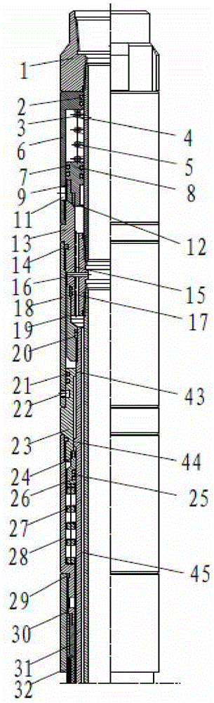
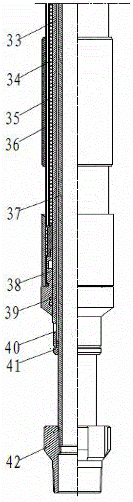
[0021] The pressure-difference water injection packer of the long-flushable rubber barrel of the present invention includes a setting assembly, a rubber barrel sealing assembly, a well-flushing assembly, and an unsealing device. It is used for layered water injection in small interlayers in medium-deep wells with small clip spacing, thick oil layer and thin interlayer tubing in the first-level two sections, two-level three-section and above water injection wells.
[0022] see attached figure 1 , 2. The upper joint 1, the upper center pipe 2, the bridge connection sleeve 13, the lower center pipe 37, and the lower joint 42 are sequentially fixed and connected by threads from top to bottom to form a fixed pipe column, wherein the connecting threads of the upper center pipe 3 and the lower center pipe 37 For external thread.
[0023] The well flushing assembly is installed on the outer circumference of the upper central pipe 3 between the upper joint 1 and the bridge connecting sleeve 13 in the axial direction; On the outer circumference of the central pipe 37; the outer circumference of the outer central pipe 33 of the setting assembly is provided with a rubber barrel sealing assembly.
[0024] The middle of the bridge-type connection sleeve 13 has a radial flow-through hole III16; the bridge-type connection sleeve 13 has an axial through hole 15 on the sleeve body.
[0025]The inner hole of the well-flushing sleeve 6 of the well-flushing assembly is a stepped hole with a small upper part and a large lower part. It is fixedly connected with the upper end of the bridge connection sleeve 13; the valve body spring 5 and the valve body 8 are installed in the annular space between the inner hole of the lower end of the well cleaning sleeve 6 and the upper central pipe 3 from top to bottom, and the valve body 8 and the well cleaning sleeve are installed from top to bottom. 6. A sealing ring 7 is installed between the inner holes, a sealing ring is installed between the valve body 8 and the upper central pipe 3; The upper central tube 3 corresponding to the valve body spring 5 has a radial flow hole I4, and the well flushing sleeve 6 corresponding to the sealing ring pressing sleeve 9 has a radial flow hole II11.
[0026] The outer threads of the two stepped outer threads at the lower end of the bridge connector (13) in the setting assembly are respectively fixedly connected with the upper connecting sleeve 18 and the inner connecting sleeve 19, and the inner connecting sleeve 19 is located in the upper connecting sleeve 18; the bridge connecting body A sealing ring 14 is installed between (13) and the upper connecting sleeve 18; a radial sealing ring 17 is installed between the bridge connecting body (13) and the inner connecting sleeve 19. The lower end of the inner connecting sleeve 19 is fixedly connected with an outer central pipe 33, and a sealing ring 20 is installed radially between the inner connecting sleeve 19 and the outer central pipe 33; There is an annular space between, and a centralizing ring 41 is installed between the lower end of the outer central tube 33 and the lower central tube 37 .
[0027] The upper connecting sleeve 18 and the valve seat 23 are positioned and connected by the unsealing scissors 22, that is, the unsealing device.
[0028] The valve seat 23 is fixedly connected with the lower connecting sleeve 28 ; a sealing ring 21 is installed radially between the valve seat 23 , the upper connecting sleeve 18 and the lower connecting sleeve 28 . The inner hole of the valve seat 23 is a small upper and lower large stepped hole. The boss II43 at the upper end slides along the outer circle of the outer central tube 33. There is an annular space between the middle part and the outer central tube 33. A valve 24 is installed in the annular space at the lower end of the valve seat 23, and a radial sealing ring 26 is installed between the valve 24 and the outer center pipe 33; the lower connecting sleeve 28 below the valve 24 and the outer center pipe The valve spring 27 is installed in the annular space between 33 .
[0029] The rubber cylinder sealing assembly is a rubber cylinder inner bag 34, a rubber cylinder elastic frame 35, an outer rubber cylinder 36, a rubber cylinder inner bag 34, a rubber cylinder elastic frame 35, a rubber cylinder inner bag 34, a rubber cylinder elastic frame 35, The length of the outer rubber cylinder 36 decreases in sequence, the two ends of the inner rubber cylinder 34 are fixedly installed with locking rings 31 , and the pressure cap 30 installed at the outer end of the locking ring 31 is fixedly connected with the inner thread of the rubber cylinder joint 32 . The rubber tube joint 32 at the upper end of the inner capsule 34 is fixedly connected with the lower connecting sleeve 28, and a radial sealing ring 29 is installed between the rubber tube joint 32 and the lower connecting sleeve 28; the rubber tube joint 32 at the lower end of the inner capsule 34 is sleeved Outside the centralizing sleeve 38, the centralizing sleeve 38 is fixedly connected with the outer central pipe 33 and is located above the radial flow hole IV40 at the lower end of the outer central pipe 33, and a radial sealing ring 39 is installed between the centralizing sleeve 38 and the outer central pipe 33 . There is a gap between the lower end surface of the outer center pipe 33 and the upper end surface of the lower joint 42, which provides space for lifting the tubing string when the unsealing operation is performed.
[0030] The elastic frame 35 of the rubber cylinder is radially superimposed into a cylindrical shape by more than 10 stainless steel sheets, and the two ends of the stainless steel sheets are fixedly connected.
[0031] Applying the present invention's well-washable long rubber cylinder pressure differential water-injection packer, the embodiment is as follows:
[0032] Running: First, the assembled well-washable long rubber cylinder differential pressure water injection packer is formed into a pipe string with other supporting tools according to the design requirements, and is fixedly connected with the tubing to form a tubing string that is lowered to the design depth.
[0033] Setting: The pressurized liquid is injected through the oil pipe, the liquid flows in through the axial through hole 15 of the bridge connecting body 13 and the annular space between the bridge connecting body 13 and the upper connecting sleeve 18 in turn, and the liquid overcomes the valve spring 27 After the valve body 25 is pushed down, it enters into the sealing cavity between the inner bag 34 of the rubber cylinder and the outer central tube 33, and the liquid pushes the inner bag 34 of the rubber cylinder, the elastic frame 35 of the rubber cylinder, and the outer rubber cylinder 36 Expansion. When the pressure reaches the design value, the outer rubber cylinder 36 is inflated and close to the inner wall of the casing. After the rubber cylinder elastic skeleton 35 is expanded and anchored to the inner wall of the casing, the outer rubber cylinder 36 seals the annular space between the oil pipe and the casing to seal off the casing. The water injection layers at the upper and lower ends of the device are separated, and the water injection operation can be carried out.
[0034] Well flushing: in the process of water injection, when well flushing is required, the well flushing fluid is injected from the annulus between the tubing and the casing, through the well flushing channel, that is, the radial flow hole II11 of the well flushing casing 6, bridge connection The axial through hole 15 of the sleeve 13, the annulus 45 of the outer center pipe 33 and the lower center pipe 37, and the radial flow hole IV40 at the lower end of the outer center pipe 33 enter the oil sleeve annulus below the rubber cylinder sealing assembly; then , the flushing fluid is returned from the tubing through the circulation valve at the bottom of the tubing string. Repeat the cycle to complete the well cleaning operation.
[0035] Unpacking: lift up the tubing string that installs the well-washable long rubber cylinder differential pressure water injection packer, connect the upper joint 1, the upper central pipe 3, the bridge connector 13, the upper connecting sleeve 18, and the inner connecting sleeve 19 in sequence. , the outer center pipe 33, the lower center pipe 37, and the lower joint 42 go up together with the tubing string until the unsealing pin 22 is cut; The sealing cavity between the bag 34 and the outer central tube 33 is connected to the flow hole IV40 at the lower end of the outer central tube 33, the hydraulic pressure in the sealing cavity is discharged from the flow hole IV40, and the inner capsule 34 of the rubber tube sealing assembly , the elastic skeleton 35 of the rubber cylinder, and the outer rubber cylinder 36 are restored to their original state and the sealing of the annulus of the tubing casing is released; The columns are raised together in the wellbore.
[0036] By adopting the differential pressure water injection packer of the present invention, the functions of setting, washing, sealing and unsealing are independently designed. interference. Under the condition that the oil casing is annularly sealed by the packer, the opening and closing of the well flushing valve can be controlled at any time through the wellhead operation. The structure design is reasonable and the performance is reliable, which is beneficial to prolong the validity period of the stratified water injection process string. , to achieve the best effect of layered water injection, and meet the needs of sub-layer water injection in small-caliber, thick oil layer and thin interlayer injection wells.
[0037] The invention not only solves the technical problem that the existing sub-injection well needs to be unsealed for regular well flushing, but also ensures the packing to the maximum extent through hydraulic setting, lifting the pipe string unsealing, and the packer does not need to be unsealed during well cleaning. Use effect and validity period of the device. At the same time, due to the use of differential pressure long rubber cylinder and its superiority in structural design, the packer not only satisfies the purpose of sealing the oil casing space and separating the water injection layer, but also solves the problem of small stuck layers or thick oil layers and thin interlayers. Divide the puzzle.
[0038] It should be noted that the above-described embodiments are examples rather than limitations of the invention, and those skilled in the art will be able to design many alternative embodiments without departing from the scope of the claims of this patent.

PUM

no PUM

Description & Claims & Application Information

We can also present the details of the Description, Claims and Application information to help users get a comprehensive understanding of the technical details of the patent, such as background art, summary of invention, brief description of drawings, description of embodiments, and other original content. On the other hand, users can also determine the specific scope of protection of the technology through the list of claims; as well as understand the changes in the life cycle of the technology with the presentation of the patent timeline. Login to view more.

Similar technology patents

Classification and recommendation of technical efficacy words

  • Functional
  • Reasonable structural design
Why Eureka
Try Eureka