An insert-type injection-molded pipe fitting and its production process

A technology of inserts and pipe fittings, which is applied in the direction of pipeline connection layout, pipes/pipe joints/pipe fittings, mechanical equipment, etc., which can solve the problems of difficult joint processing, poor pipeline sealing, and low pressure resistance, and achieve effective and stable connection and sealing Good sex and strong overall effect

Active Publication Date: 2017-08-25
山东华信塑胶股份有限公司
View PDF6 Cites 1 Cited by
  • Summary
  • Abstract
  • Description
  • Claims
  • Application Information

AI Technical Summary

Problems solved by technology

The above-mentioned joints are difficult to process, high in cost, and complicated in process, and the pipelines connected by this connection method have poor sealing performance, low compression resistance, and poor stability.

Method used


Image

  • An insert-type injection-molded pipe fitting and its production process
  • An insert-type injection-molded pipe fitting and its production process
  • An insert-type injection-molded pipe fitting and its production process

Examples


Embodiment 1

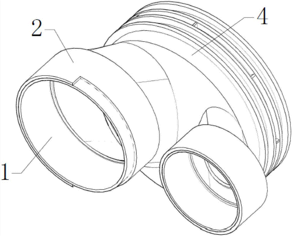
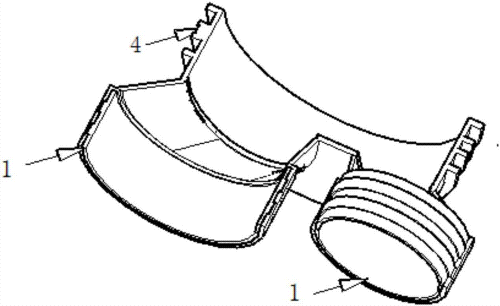
[0039] Such as Figure 1-2 shown.

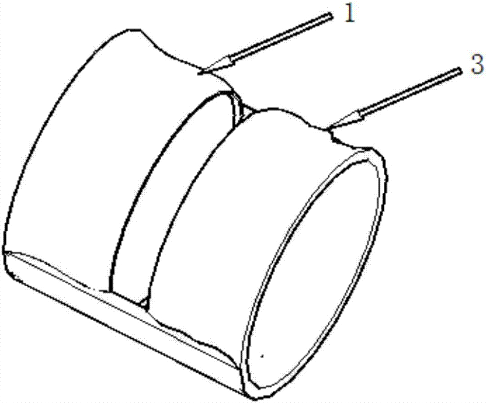
[0040] An insert-type injection-molded pipe fitting joint for a 250×160 / 110 confluence tee in an inspection well, comprising an insert 1 and a main body of the pipe, the insert 1 and the main body of the pipe are connected by injection molding; the main body of the pipe Including the joint part 4 and the joint part 2, the joint part 4 is airtightly and fixedly connected with the joint part 2; the insert 1 and the joint part 2 are socketed; the outer wall of the insert 1 is provided with three annular protrusions 3, the ring The protrusion 3 surrounds the outer surface of the insert 1 for a week; the inner wall of the connecting part 2 is provided with a groove corresponding to the shape of the annular protrusion 3, and the groove surrounds the inner wall of the connecting part 2 for a week; the annular protrusion 3 The insert is arranged in the groove; the material of the insert 1 is consistent with that of the pipe to be connected; the ins...

Embodiment 2

[0042] As described in Example 1, an insert-type injection-molded pipe fitting joint for a 250×160 / 110 confluence tee in an inspection well, the difference is that: the insert 1 is made of PVC / CPVC; the main part of the pipe fitting is Polyolefin material. PVC / CPVC pipes have high strength and can meet the strength requirements when the pipe wall is relatively thin; polyolefin has good fluidity and is easy to process.

Embodiment 3

[0044] As described in Example 1, a 250×160 / 110 fusion tee insert type PVC / CPVC pipe joint for inspection wells, the difference lies in: the corner of the raised part of the annular protrusion 3 and the protrusion The corners where the raised portion 3 contacts the outer side wall of the insert 1 are arc-shaped. The advantage of the design here is that not only the contact area between the insert 1 and the connecting part 2 is further increased, the connection is more stable, and the sealing and stability of the joint are further improved, but also the arc-shaped structure is conducive to the fluid flow inside the joint to prevent or Reduce the impact damage of the main material to the insert structure and prolong the service life.


PUM


Abstract

The invention relates to an insert-type injection pipe joint. The insert-type injection pipe joint comprises an insert and a pipe main body part, wherein the pipe main body part comprises a combination part and a connecting part; the combination part is fixedly connected with the connecting part in an airtight manner; the insert is connected with the connecting part in a sleeving manner; the insert-type injection pipe is characterized in that an annular bulge is arranged on the outside wall of the insert; the annular bulge surrounds the periphery of the outer surface of the insert; a groove which corresponds to the annular bulge is formed in the inside wall of the connecting part; the groove surrounds the periphery of the inside wall of the connecting part; the annular bulge is embedded into the groove; the contact area between the insert and the connecting part can be increased by embedding the annular bulge into the groove, so that the combination strength of the pipe joint can be improved; the insert is combined with the pipe main body part in an injection mode, and the machining difficulty cannot be increased because of the thickness of the wall of the insert.

Description

[0001] Technical field: [0002] The invention relates to an insert-type injection molding pipe fitting joint and a production process thereof, belonging to the technical field of pipe joints. [0003] Background technique: [0004] In today's life, pipeline facilities play an important role in drainage, sewage, network communication and other fields. The rapid and effective connection of pipelines is an important part of the effective function of pipeline facilities. [0005] Connecting the pipe fittings by injection molding will not increase the difficulty of processing due to the thickness of the wall of the processed pipe fittings. In the prior art, the connection of pipe fittings is usually connected by mechanical methods such as apron connection, flange connection, steel-plastic transition joint; for apron connection, it is relatively difficult to process the groove mold of the apron of small-aperture pipe fittings, and it is difficult to realize, and according to This m...

Claims


Application Information

Patent Timeline
Patent Type & Authority Patents(China)
IPC IPC(8): F16L47/02F16L47/26B29C45/14
CPCB29C45/14F16L47/02F16L47/32
Inventor 汤毅潘大任赵际伟
Owner 山东华信塑胶股份有限公司
Why Eureka
Try Eureka