Combined thermal dynamic system

A technology of power linkage and power engine, which is applied in the field of combined heat and power supply and heat pump, and can solve the problem of no cold environment utilization.

Active Publication Date: 2015-05-27
李华玉
View PDF6 Cites 14 Cited by
  • Summary
  • Abstract
  • Description
  • Claims
  • Application Information

AI Technical Summary

Problems solved by technology

However, none of these combined heat and power techn

Method used


Image

  • Combined thermal dynamic system
  • Combined thermal dynamic system
  • Combined thermal dynamic system

Examples


Embodiment Construction

[0070] The first thing to explain is that in the expression of the structure and process, it will not be repeated if it is not necessary; the obvious process will not be expressed. The present invention will be described in detail below in conjunction with the accompanying drawings and examples.

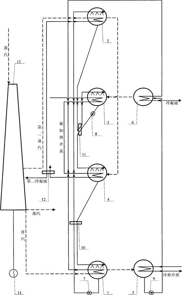
[0071] figure 1 The combined heat and power system shown is realized in this way:

[0072] (1) Structurally, it mainly consists of generator, second generator, absorber, second absorber, condenser, evaporator, solution pump, second solution pump, refrigerant liquid pump, solution heat exchanger, first Two solution heat exchangers, heat exchangers, a power machine and a working machine are formed; the power machine 13 is connected to the working machine 14, and the power machine 13 has a fresh steam passage to communicate with the outside, and the power machine 13 also has an exhaust steam passage to communicate with the outside, and the power machine 13 also has an exhaust steam pa...


PUM


Abstract

The invention provides a combined thermal dynamic system, which belongs to the technical field of thermal dynamic combination and heat pumps. Power is supplied to a working machine by a power machine, exhaust steam is supplied to a generator and an evaporator by the power machine, middle extraction steam is supplied to a second generator and a heat exchanger by the power machine, the generator is communicated the second generator through a solution pump and a solution heat exchanger, the second generator is communicated with an absorber through a second solution heat exchanger, the absorber is communicated with a second absorber through a second solution pump and the second solution heat exchanger, the second absorber is communicated with the generator through the solution heat exchanger, refrigerant steam is supplied to the second absorber by the second generator, the generator is provided with a refrigerant steam channel which is communicated with a condenser, the condenser is communicated with the evaporator through a refrigerant liquid pump, the evaporator is provided with a refrigerant steam channel which is communicated with the absorber, the condenser is provided with a cooling medium pipeline which is communicated with the outside, and the absorber, the second absorber and the heat exchanger are respectively provided with heated medium pipelines which are communicated with the outside, so as to form the combined thermal dynamic system.

Description

Technical field: [0001] The invention belongs to the technical field of thermodynamic (electricity) cogeneration and heat pump. Background technique: [0002] In the thermodynamic cycle device using water vapor as the circulating medium, in order to make the power machine (steam turbine) have a higher internal thermal efficiency and increase its operational safety and reliability, it is required that the pressure and temperature of the exhaust steam of the power machine should not be too low; , the ambient temperature is low, and the exhaust temperature of the power engine is high, there will be a temperature difference of about 40°C or even higher between the two, which cannot be utilized; moreover, in the steam power cycle system represented by thermal power plants, Although the grade of the exhaust steam is very low, the remaining heat load is often very rich, and it is of great significance if it can be used effectively. [0003] The existing combined heat and power sup...

Claims


Application Information

Patent Timeline
IPC IPC(8): F25B15/02F25B27/02
CPCY02A30/274Y02B30/625F25B15/025F25B27/02F25B2315/00
Inventor 李华玉
Owner 李华玉
Why Eureka
Try Eureka