
Flow guide device for air-cooled unit with Delta-shaped passage spaces

A technology of a diversion device and a channel-shaped channel is applied in the field of the diversion device of an air-cooling unit, which can solve the problems of poor cooling effect, increased fan outlet resistance, and uneven distribution of air flow resistance, so as to improve cooling performance, avoid eddy currents, and improve cooling. effect of effect

Active Publication Date: 2015-05-27
GUODIAN LONGYUAN POWER TECH ENG
View PDF4 Cites 9 Cited by
  • Summary
  • Abstract
  • Description
  • Claims
  • Application Information

AI Technical Summary

Problems solved by technology

[0004] Since the air-cooling unit is an "A"-shaped frame structure, at the three angles of the triangular △ channel space surrounded by it, the resistance of cooling air flowing through the finned heat dissipation tubes (also called air-cooled finned tube bundles) must be greater than other places. As a result, the cooling air forms a vortex at this place, which deteriorates the heat transfer effect of the finned heat pipe at this place, and at the same time increases the outlet resistance of the fan, resulting in an increase in power consumption
Therefore, the existing "A" frame structure is not optimal, and the air flow resistance is unevenly distributed along the direction of the finned cooling tubes, resulting in low utilization of the finned cooling tubes, resulting in poor cooling effect and low performance of the direct air cooling system

Method used


Image

  • Flow guide device for air-cooled unit with Delta-shaped passage spaces
  • Flow guide device for air-cooled unit with Delta-shaped passage spaces
  • Flow guide device for air-cooled unit with Delta-shaped passage spaces

Examples


Embodiment Construction

[0028] In order to make the object, technical solution and advantages of the present invention clearer, the implementation manner of the present invention will be further described in detail below in conjunction with the accompanying drawings.

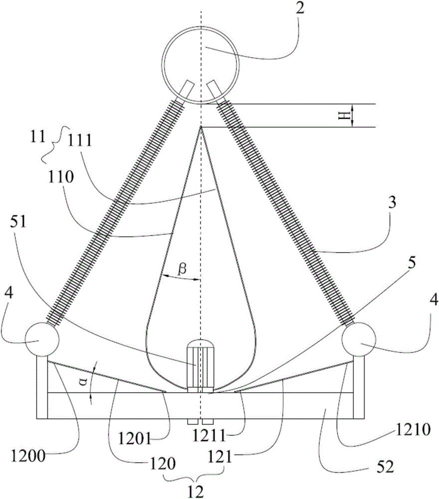
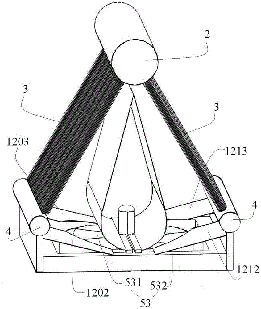
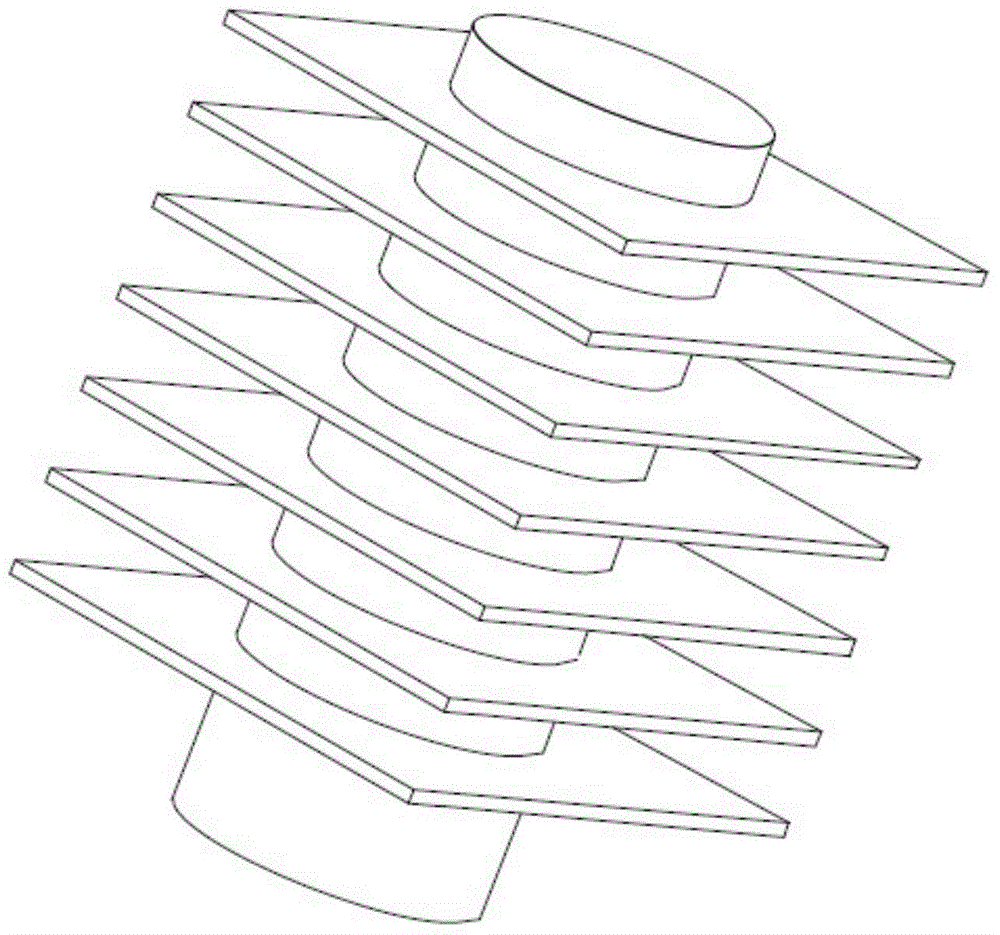
[0029] In areas with a lot of coal and water shortage, thermal power generating units mainly adopt direct air cooling technology. The direct air-cooling system adopting this technology includes a plurality of air-cooling units, and any one of the air-cooling units is an "A" frame structure, which includes: air-cooling finned tube bundles 3 (each A tube bundle 3 is made up of a plurality of tubes 31 with fins 32 on it, and the configuration relationship between the fins 32 and the tubes 31 is as follows: image 3 As shown), the condensate pipe 4 is connected to the lower end of the air-cooled fin tube bundle 3, and the air-cooling fan 5 is arranged below the air-cooling fin tube bundle 3, and the air-cooling fan 5 is fixed below the air...


PUM


Abstract

The invention discloses a flow guide device for an air-cooled unit with a Delta-shaped passage spaces. The air-cooled unit comprises a steam distribution pipe, downwards-inclined air-cooled finned tube bundles connected with the two sides of the steam distribution pipe respectively, condensate water pipes connected with the lower ends of the air-cooled finned tube bundles and an air-cooled fan arranged below the air-cooled finned tube bundles, wherein the air-cooled fan is fixedly arranged below the air-cooled finned tube bundles through an air-cooled fan frame; the steam distribution pipe, the air-cooled finned tube bundles, the condensate water pipes and the air-cooled fan enclose the Delta-shaped passage space. The flow guide device comprises a top flow guide mechanism arranged on the middle part of the Delta-shaped passage space and a bottom flow guide mechanism arranged at the bottom of the Delta-shaped passage space, wherein e top end of the top flow guide mechanism is at a certain distance far away from the bottom end of the steam distribution pipe; the bottom end of the top flow guide mechanism is connected with the air-cooled fan frame; the top flow guide mechanism and the bottom flow guide mechanism are integrated or independent. According to the scheme, cooling effects of the air-cooled unit are improved, and the cooling performance of a direct air-cooled system is improved.

Description

[0001] This application is a divisional application of a patent application with an application date of June 25, 2013, an application number of 201310256002.2, and an invention title of "Flow Guide Device for Air Cooling Unit". technical field [0002] The invention belongs to the technical field of power station air cooling, and in particular relates to a flow guiding device of an air cooling unit with a delta-shaped channel space. Background technique [0003] In areas rich in coal and short of water, in order to improve economic benefits, thermal power generating units mainly adopt direct air cooling technology. The direct air-cooling system using this technology includes multiple air-cooling units, any one of which is an "A"-shaped frame structure, which includes: downwardly inclined air-cooling finned tube bundles connected to both sides of the steam distribution pipe respectively, in the air-cooling fin The lower end of the fin tube bundle is connected with a condensat...

Claims


Application Information

Patent Timeline
Patent Type & Authority Applications(China)
IPC IPC(8): F28B9/00
Inventor 赵虎军姜媛媛腾东玉王文波王公林
Owner GUODIAN LONGYUAN POWER TECH ENG
Learn More