Three-dimensional imaging sonar beamforming method and its implementation on multi-core processor

A multi-core processor and sonar technology, applied in the field of sonar, can solve the problems of low real-time performance, large amount of calculation, and long time consumption, and achieve the effect of high real-time performance, small amount of calculation, and easy realization

Active Publication Date: 2017-05-17
INST OF ACOUSTICS CHINESE ACAD OF SCI
View PDF4 Cites 0 Cited by
  • Summary
  • Abstract
  • Description
  • Claims
  • Application Information

AI Technical Summary

Problems solved by technology

[0004] The purpose of the present invention is to overcome the defects of large amount of calculation, long time consumption and low real-time performance existing in the three-dimensional imaging sonar in the prior art when performing array beamforming, thereby providing a sonar with a small amount of calculation and high real-time performance. beamforming method

Method used


Image

  • Three-dimensional imaging sonar beamforming method and its implementation on multi-core processor
  • Three-dimensional imaging sonar beamforming method and its implementation on multi-core processor
  • Three-dimensional imaging sonar beamforming method and its implementation on multi-core processor

Examples


Embodiment Construction

[0025] The present invention will now be further described with reference to the accompanying drawings.

[0026] Before the present invention is described in detail, related concepts involved in the present application are first described.

[0027] Three-dimensional imaging sonar plane array: The plane array is a uniformly distributed plane array, including M×N array elements.

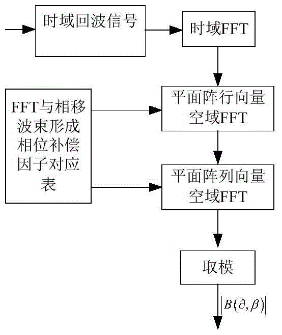
[0028] 3D Imaging Sonar Planar Array Beamforming Expression

[0029] The general expression for beamforming of a 3D imaging sonar planar array is:

[0030]

[0031] where: is the beam direction unit vector; s m.n (t) is the time domain signal received by the (m, n)th array element; α m.n is the coefficient of the window function, which is used to adjust the side lobe level after beamforming; τ(r 0 ,u,m,n) is the distance of the (m,n)th array element to the target r 0 The delay parameter at , the delay parameter is:

[0032]

[0033] In the formula: v=(x m ,y n ,0) is the coordinate posi...


PUM


Abstract

The invention relates to a three-dimensional imaging sonar wave beam forming method applied to uniformly-distributed plane arrays in three-dimensional detection sonar. The method comprises the following steps: receiving and collecting time domain echo signals; carrying out time domain Fourier transform on the time domain echo signals, then judging whether the result obtained by the time domain Fourier transform meets the far-field condition or not, compensating distance influence items of a time delay calculation formula in a near-field wave beam forming expression formula, and then carrying out the next step if the result shows that the near-field wave beams are formed; directly carrying out the next step if the result shows that far-field wave beams are formed; carrying out spatial Fourier transform on row vectors of the plane arrays of the signals; carrying out spatial Fourier transform on line vectors of the plane arrays of the signals; performing a modulus on the obtained spatial two-dimensional Fourier transform result to obtain a final two-dimensional wave beam forming result.

Description

technical field [0001] The invention relates to the field of sonar, in particular to a three-dimensional detection sonar beam forming method and an implementation method on a multi-core processor. Background technique [0002] The security defense, attack, and penetration of the nearshore and port are an important mission of the frogman fighting force. In addition, the frogman's work also includes tasks such as reconnaissance of underwater terrain, measurement of water depth, detection and removal of underwater obstacles, and underwater combat. . The three-dimensional detection sonar is a sonar device that assists the frogman in high-efficiency underwater detection. 3D detection sonar is an area array sonar system with sparsely arranged array elements, which can perform 3D high-resolution imaging of underwater targets. Handheld 3D detection sonar can be used for underwater special reconnaissance operations, underwater terrain, frogmen and small target detection, collision ...

Claims


Application Information

Patent Timeline
Patent Type & Authority Patents(China)
IPC IPC(8): G01S7/52
CPCG01S7/539
Inventor 王朋黄勇黄海宁刘纪元
Owner INST OF ACOUSTICS CHINESE ACAD OF SCI
Why Eureka
Try Eureka