Intelligent vehicle system

A smart car and controller technology, which is applied in the field of smart car systems, can solve the problems of slow running speed, instability, and high center of gravity on curves, and achieve the effects of reducing total weight, stable performance, and light weight

Inactive Publication Date: 2015-05-27
赵宝瀛
0 Cites 1 Cited by

AI-Extracted Technical Summary

Problems solved by technology

However, there are still some problems in the existing smart cars, such ...

Abstract

The invention discloses an intelligent vehicle system, and relates to an improvement on the intelligent vehicle system. The intelligent vehicle system of the invention is stable in performance and fast in curve running speed. The intelligent vehicle system comprises a controller, a motor, a comparator, a fan, an actuator, an airflow sensor, a speed sensor, a voltage-stabilizing circuit, an LED, a memory, and a power supply, and is characterized in that the speed sensor, the airflow sensor and the voltage-stabilizing circuit are connected with an input port of the controller; the output port of the controller is connected with the actuator, the motor and the LED; and the controller is also connected with the power supply and the fan.

Application Domain

Position/course control in two dimensions

Technology Topic

Electric machineryAutomotive engineering +5

Image

  • Intelligent vehicle system

Examples

  • Experimental program(1)

Example Embodiment

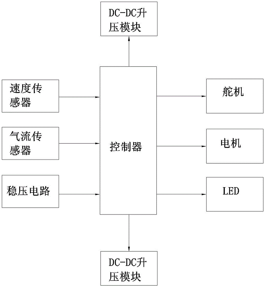
[0010] As shown in the figure, the present invention includes a controller, a motor, a comparator, a fan, a steering gear, an airflow sensor, a speed sensor, a voltage stabilizing circuit, an LED, a memory, and a power supply. The input port of the controller is connected; the output port of the controller is connected with the steering gear, the motor, and the LED; the controller is also connected with the power supply and the fan.
[0011] The controller of the present invention is an XS128 chip.
[0012] The intelligent vehicle positioning system of the present invention uses a laser tube and a receiving chip to detect the track in front of the vehicle, and obtains track data by sampling the analog signal of the phototransistor through MC9S12XS128, and combines certain algorithms to extract the black and white lines of the track to drive the steering gear and the motor Chip with proper control.
[0013] The steering of the steering gear is a link with greater delay in the entire control system. Under the same steering gear conditions, the farther the connection point of the steering link at one end of the steering gear is from the axis of the steering gear, the faster the steering wheel steering changes. The advantages of this installation are: the moment arm of the steering gear is changed to make the steering more sensitive; the steering gear is installed in the center to make the left and right steering basically the same; the center of gravity is relatively rearward, reducing the load of the steering gear.
[0014] Adjustment of the rear wheelbase: When the car is running at high speed, it is easy to overturn when turning suddenly. In order to increase the balance ability of the whole car, the original rear wheel adjustment part of the car model can be changed to a large wheelbase adjustment part, so that the rear wheelbase is in the original Based on the increase of 4mm, the sideslip is further reduced.
[0015] The adjustment of front wheel parameters includes front wheel kingpin caster angle, kingpin inclination angle, front wheel camber angle, and front wheel toe. These parameters have a very important influence on the stability of the car body in a straight line and the flexibility of turning.
[0016] Fix the laser tube in the lower row of holes and the upper row of six fixed receiving tubes and lenses, and adjust the laser irradiation distance to 50CM, and the forward-looking effect is the best.
[0017] The lower the center of gravity, the better. When choosing a camera, choose a lighter one, the material and specifications of the camera bracket should also be considered, and the placement of the circuit board should be as low as possible.
[0018] It is understandable that the above specific description of the present invention is only used to illustrate the present invention and is not limited to the technical solutions described in the embodiments of the present invention. Those of ordinary skill in the art should understand that the present invention can still be modified or modified. Equivalent replacement to achieve the same technical effect; as long as the use needs are met, it is within the protection scope of the present invention.

PUM

no PUM

Description & Claims & Application Information

We can also present the details of the Description, Claims and Application information to help users get a comprehensive understanding of the technical details of the patent, such as background art, summary of invention, brief description of drawings, description of embodiments, and other original content. On the other hand, users can also determine the specific scope of protection of the technology through the list of claims; as well as understand the changes in the life cycle of the technology with the presentation of the patent timeline. Login to view more.

Similar technology patents

Vacuum-Stabilized Ablation System

ActiveUS20100081987A1improve stability
Owner:ST JUDE MEDICAL ATRIAL FIBRILLATION DIV

Monitoring system based on J2EE framework and method

InactiveCN101847116AImprove stabilityspeed up development time
Owner:ZTE CORP

Coverage rate test processing method and device and coverage rate test server and system

ActiveCN103095518AImprove stabilityReduce the probability of failure
Owner:ALIBABA GRP HLDG LTD

Classification and recommendation of technical efficacy words

  • small size
  • Improve stability

Microfabricated elastomeric valve and pump systems

InactiveUS6929030B2high speedsmall size
Owner:CALIFORNIA INST OF TECH

RFID antenna

InactiveUS20060208900A1high efficiencysmall size
Owner:TRANSPACIFIC TECH

Capacitor module, power converter, vehicle-mounted electrical-mechanical system

ActiveUS20070109715A1reduce surge voltagesmall size
Owner:HITACHI ASTEMO LTD

Projection display chip

InactiveUS20100321640A1small sizehigh efficiency
Owner:IND TECH RES INST

Phase-change energy-storage material nanocapsule and preparation method thereof

ActiveCN104449590Asmall sizeImprove stability
Owner:INST OF CHEM MATERIAL CHINA ACADEMY OF ENG PHYSICS
Why Eureka
Try Eureka